LED lighting penetrates everybody’s life, becoming more intelligent and more sophisticated. When designing high quality and excellent luminaire, the design engineer must carefully understand the LED Driver since it is the heart of a light fixture. This article describes the most frequently used LED driver concepts and provides the methods to select a suitable and qualified LED driver.
1. What is LED driver
LED Driver, also named as LED power supply, converts typically Alternating Current (AC) into a regulated Direct Current (DC) output because the light-emitting diodes (LED) is a unique component that only accepts Direct Current input.
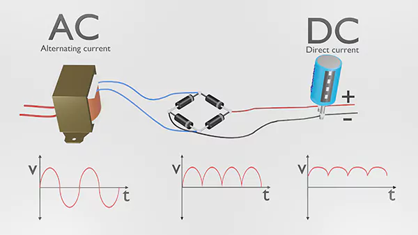
Don’t know what AC and DC are? This article explains everything.
Download this page as a PDF
To save you time, we have also prepared a PDF version containing all the contents of this page, only leave your email and you will get the download link immediately.
2. Dimensions to Describe LED Driver
a. External vs. Interior LED driver
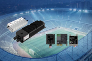
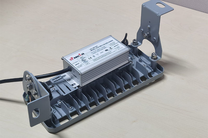
LED drivers can be built inside a lamp (Interior), put on the surface of a light fixture, or even put outside a fixture (External). Most of the low power indoor lights especially bulbs adopt interior LED drivers to make a lower cost and better-looking product but the external LED drivers are frequently used for downlights and panel lights.

And as the power further increases, the thermal situation inside the lights becomes worse, thus external LED drivers are more adopted in high power applications like street lights, floodlights, stadium lights and grow lights. The other advantage external LED Driver has is an easy replacement for maintenance.
b. Switching Power Supply vs. Linear Regulator
Linear LED drivers are often seen in AC LED, signage and strip applications and it is so simple that a resistor or a regulated MOSFET or IC can finish the job of making a constant current for LED. So it is very easy for power supplies to adapt and allows a super wider range of choices of constant voltage power supplies such as 12V, 24V LED drivers. The drawback of a linear regulator is that the power loss is high thus the light efficacy can not be as high as switching power supplies.
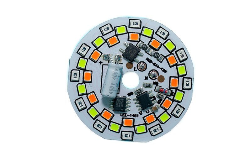
And obviously, the great advantage of switching supply is the high efficiency which results in high light efficacy which is the key parameter for most light applications. And compared with AC LED, switching power supply has a higher power factor, surge immunity and less flickering.
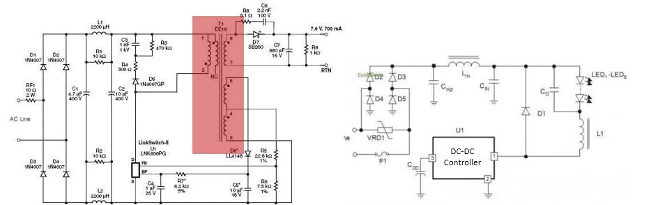
c. Isolated vs. Non-isolated LED Driver
When we compare those two items, both are referred to as switching power supplies. The isolated design has adequate voltage insulation between input and output, and normally it is 4Vin+2000V according to UL and CE and 3750Vac according to 3C standards. The insulation prevents the high input voltage from penetrating to output thus improving safety and sacrificing the efficiency (~-5%) and cost (~+50%) by using a highly insulated transformer rather than an inductor as the manpower transferring component. Non-isolated design is just the opposite, and it is mainly adopted in low power built-in designs.
d. Constant current vs. Constant voltage LED Driver
There is no doubt that LED should be driven by a constant current source due to LED special V-I characteristic, but when there is a linear regulator or resistor in series with the LED to provide the current limitation, a constant voltage LED driver can be used. We also prepared another article for you if you want to learn how to dim your LED strips. Due to the much higher efficiency, constant current LED Driver is the mainstream for general lighting like bulbs, linear lights, downlights, street lights etc. while constant voltage LED drivers with 12V, 24V even 48V are used for signage and strip as the main solution. By using the constant voltage solution, it is very easy for users to configure the amount of light as long as the total power does not exceed the power supply rating thus it provides a lot of flexibility for field installation. We also have another article to explain the Difference Between Constant Voltage And Constant Current LED Drivers.

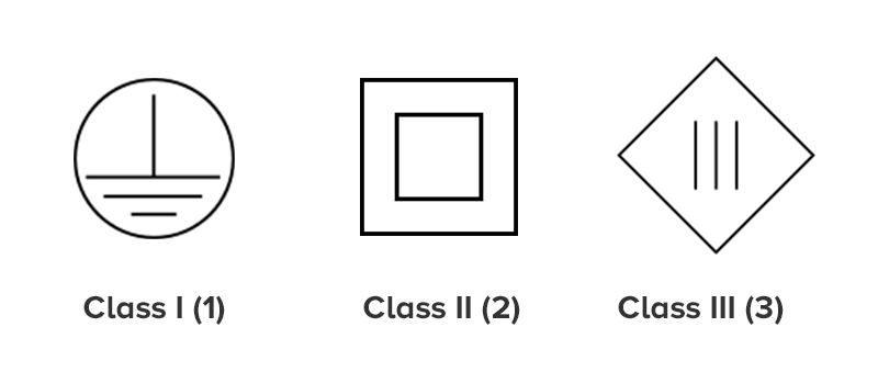
e. Class I vs. Class II LED Driver
Here I and II are written in Roman numerals, rather than 1 and 2, which has totally different meaning shown in the next item. Class I and class II are the concepts from IEC (International Electro-technical Commission) standards while they both define the internal construction and electrical insulation of a power supply so as to provide safety against electric shock. IEC Class I input LED drivers have basic insulation and shall have protective earth (ground) connection to eliminate the electric shock. IEC Class II input models feature additional safety precautions such as double insulation or reinforced insulation, thereby there is no need for a protective earth (ground) connection. In general, class I LED Driver has ground cable at the input side and class II does not have but has a higher insulation level from input to either enclosure or output. And here is the normally used symbols for class I and class II.
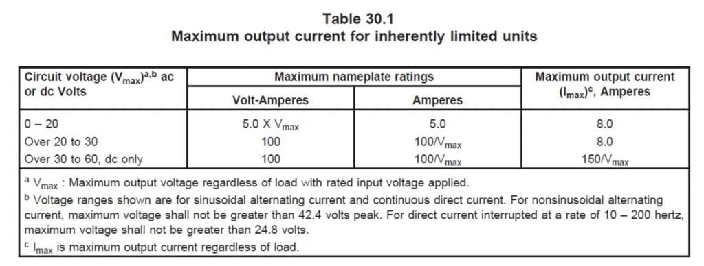
f. Class 1 vs. Class 2 LED Driver
Using the Arabian numerals, class 1 and class 2 are NEC (National Electric Code) concepts describing the output feature of a power supply output with less than 60Vdc in dry location/30Vdc in a wet location, less than 5A current, and less than 100W power, as well as the detail requirement for the circuit design feature. UL Class 2 LED driver is regulated by UL1310 and UL8750, and there is quite a lot of benefits using class 2 LED driver whose output is considered as safe terminal and no extra protection is required at the LED modules or light fixtures thus it saves cost for insulation and safety test. However, these limitations pose restrictions on the number of LEDs a Class 2 LED driver can operate.
UL Class 1 include all the LED drivers out of the range of class 2 and is regulated by UL1012 and UL8750. Although class 2 LED drivers have good advantages of simplifying the safety design of the light fixture, class I LED drivers are still widely used because of higher efficiency and more uniform light output due to the lower output current and having more LEDs in series. In real applications, class 2 LED drivers are more used in the lights which are easy to be touched by users, such as grow lights, while class 1 LED drivers are more adopted in highly mounted lights such as stadium and pole lights.
g. Dimmable vs. Non-dimmable LED Driver
Each light is born to be dimmed in this new era. This is a big topic since there are quite a few dimmable schemes and let’s introduce them one by one.
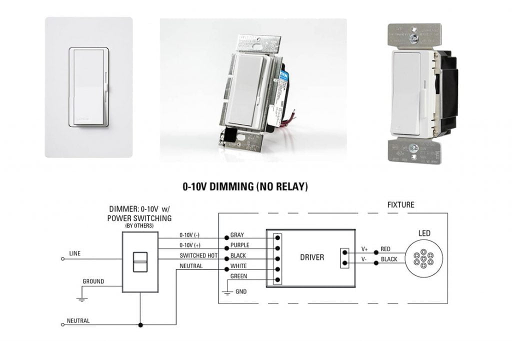
1) 0-10V/1-10V dimming LED Driver
It is also called analog dimming and is most widely used. It was derived from the era of fluorescent and defined by IEC60929 Annex E.

The drawback of this control scheme is that the dimming cable can have a voltage drop if the cable is long thus the consistency of the lights can not be ideal. Also, each LED Driver may need 100-500uA dimming control current from the master controller thus the maximum quantity of a lighting system is always limited. More about 0-10V dimming.
2) PWM dimming LED Driver
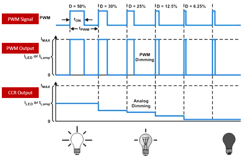
To overcome the drawback of 0-10V dimming, PWM (Pulse Width Modulation) dimming is utilized for more and more projects though the popularity is still far less than 0-10V. PWM signed is generated by the master as a digital signal, thus the signal on the dimmable cable can be very consistent. PWM duty cycle is detected by the LED Driver to determine the output current. Now there are two methods to realize PWM dimming LED driver in the market, one is “fake” PWM dimming, there is RC (resistor-capacitor) filter inside the LED Driver and the PWM dimming signal is filtered to a DC voltage which is proportional to PWM duty cycle. The drawback of this method is that the peak value of the PWM signal must be 10V, otherwise, the accuracy is very bad. Also, the frequency of the PWM signal is limited by the RC parameter. The typical application is Meanwell HLG/ELG/XLG series LED drivers. The other one is real PWM dimming and there is MCU inside the LED Driver thus PWM signal with any peak voltage can be detected, also the allowable PWM frequency range can be much wider than RC way. uPowerTek LED drivers are all MCU integrated to work with PWM dimming. And there are two different things easily mixed when we talk about PWM dimming, PWM signal dimming and PWM output dimming and the figure below shows the detail of the difference. In this section, PWM dimming means PWM signal dimming, while PWM output dimming circuitry chops the DC LED current between the on/off state in a high frequency thus the human eye is not able to perceive the flicker thus changing the light output of the LED.
Still don’t understand PWM dimming, we have more words and images to explain this topic, What is PWM dimming for LED Driver?
3) Triac dimming LED Driver
It is also called phase-cut dimming or leading/trailing edge dimming and was the popular way in the incandescent lamp era. Leading-edge has a major role in Triac dimming application. Triac dimming is the old and bad way to dim the LED lights where the “noise” is high on both the human ear and cable

4) DALI dimming LED Driver
DALI stands for Digital Addressable Lighting Interface. It is illustrated by the international standard IEC62386 series as the first lighting digital protocol with bi-directional communication. As the first generation, DALI 1 system consists of a controller and a maximum of 64 ballasts or LED drivers given independent addresses. More about DALI dimming. In the year 2017, the DiiA Digital Illumination Interface Alliance announced the second generation DALI 2 which supports 128 max devices and has much greater compatibility between the devices from different brands. DALI 2 also support sensors. Both DALI 1 and DALI 2 devices have to be tested by the professional DALI tester Probit, then certified and shown on the DiiA website. Want to Know the Difference Between DALI and DALI-2, please read this article. At the same time, the D4i concept was released to indicate the devices which have not only DALI 2 compatibility but also the functions of energy report, data transmission, diagnose&maintenance and memory bank.

5) DMX dimming LED Driver
Also named DMX512 (“Digital Multiplex with 512 pieces of information”), it is a standard for digital communication networks that are commonly used to control stage lighting and effects. For general lighting, DMX512 protocol is mostly used for stadium lights and architectural applications and is not very popular for other than those. This is a broadcasting way like PWM rather than DALI which is able to feedback, and the difference from PWM is that DMX512 devices have individual addresses so as to control one by one.
Want to know more about DMX dimming? Please read this article, What Does DMX Mean in Lighting?

6) Other Protocols of LED Driver
There are quite a few other protocols that are often adopted in lighting systems, such as wired solutions like PLC, KNX, RS485, CAN and wireless ones like LoRa, Bluetooth, Zigbee, but none of them are designed for lighting application only. The lighting industry is making efforts to make sure a dedicated lighting protocol will be developed on one of them especially the wireless solution.
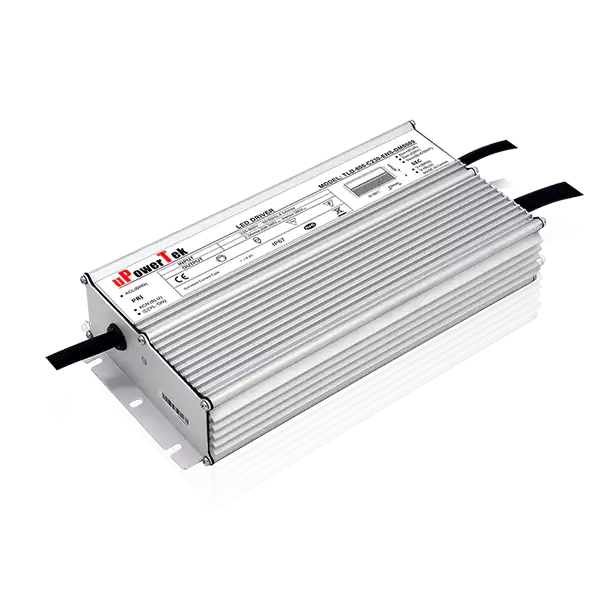
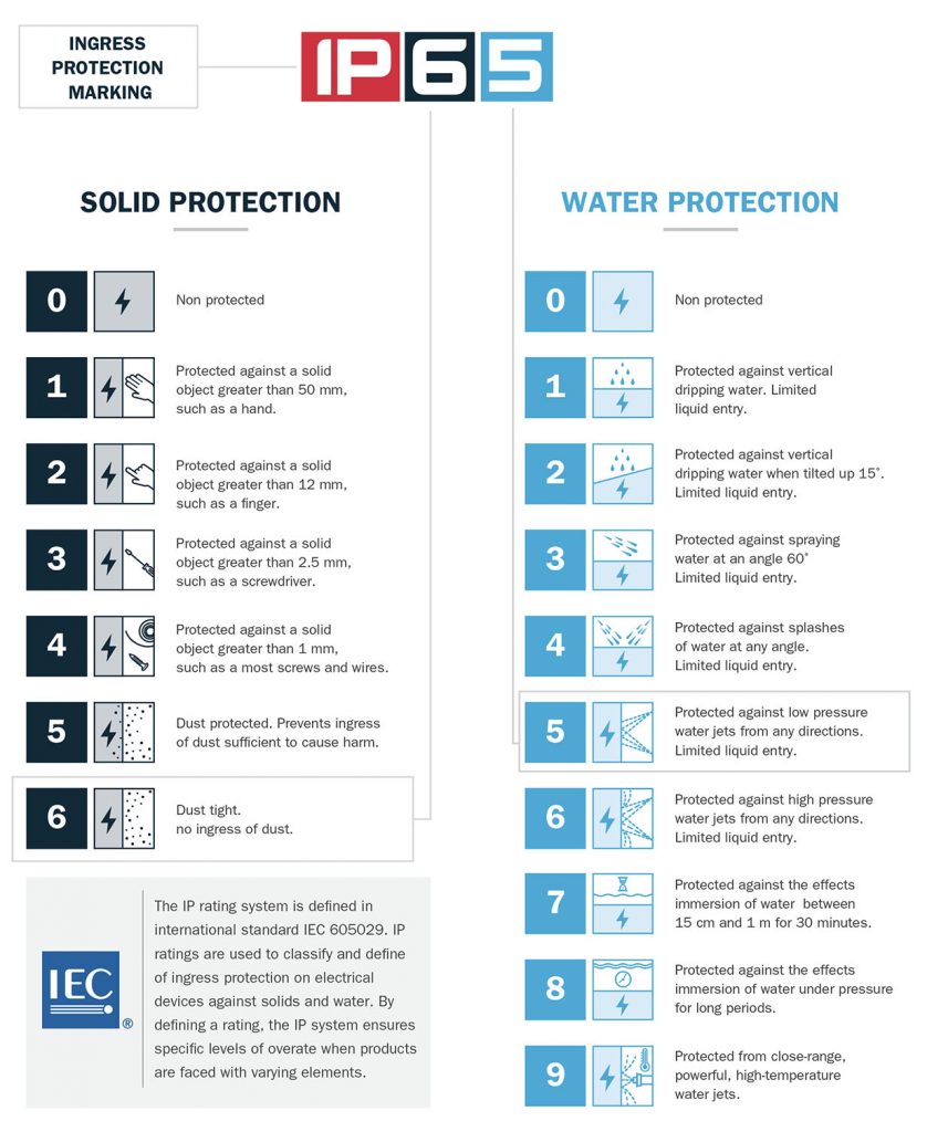
h. Waterproof vs. Non-waterproof LED Driver
IP (ingress protection) rating is the only way to describe the waterproof level of LED drivers and is regulated in IEC60529. The IP code is composed of two numerals, the first numeral refers to the protection against solid objects using a scale from 0 (no protection) to 6 (no ingress of dust) while the second numeral rates the protection against liquids using a scale from 0 (no protection) to 7 (8 and 9 are rarely seen in lighting industry). It is obvious that waterproof LED drivers are used for outdoor applications and IP20 or other low IP rated LED drivers are used for indoor. But it is not always true, some indoor application adopts waterproof LED drivers only because they can deliver much higher power than low IP ones without an active cooling system which has a shorter life than IP rated LED drivers.
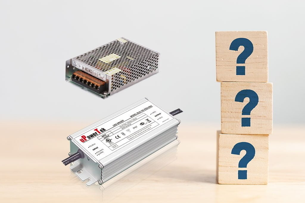
3. How to Choose a Suitable LED Driver
Choosing a suitable LED driver is one of the basic steps for designing a great luminaire, and let’s see how to make it.
a. Position the LED Driver
Determine the design is a performance competing one or a cost-effective one. Understand who the competitors are and what the cons and pros they have.
b. Go through [section 2: dimensions to describe a LED driver]
and find the answers for your luminaire design.
c. Understand the LED Driver input voltage
You should know where the target market is and thus decide the input voltage range. Here it is the global mains electricity voltage map.
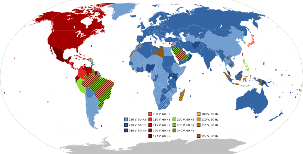
This map only listed the single-phase voltage, and there is a lot of 3 phase application thus the voltage has to be multiplied by √3 or 1.732 for 3 phase usage. Designing narrow input voltage helps to decrease the cost, but increase the models for different areas of the world. But too wide an input voltage range increases the cost and reduce the performance. Thus the most balanced input voltage range in the industry is 100-277Vac (uPowerTek BLD series) and 200-480Vac (TLD series).
d. Find the right LED Driver output voltage
current and power. It is easier for constant voltage type LED drivers to decide the model because of fewer choices. The typical outputs are 12V, 24V and maybe 48V so users only have to decide the power. For constant current LED drivers, there are so many choices of output current and voltage thus making the LED driver industry very diversified. Once the lumen output is determined when making a fixture design, the power needed to drive the LED is clear by judging the LED light efficacy. Then design has to decide if high voltage/low current or high current/low voltage LED should be employed. There are a lot of considerations and no “always correct” answers to this question. High voltage low current can give the light fixture higher efficacy because of the higher LED driver efficiency, and better LED consistency without worrying about the imbalance of different LED strings, however, there is extra cost generated due to the higher insulation cost. And the low voltage high current design is just the opposite. And different light designers have different thinking of how to choose, but there are some special lights that do not have too many choices. For example, low bay grow lights which are installed at a height that people are easy to touch, have to use low voltage high current for safety consideration. Also for some high bay or pole lights that use the remotely mounted LED drivers for weight and maintenance, high voltage low current LED drivers are the mainstream to save the output cable cost.
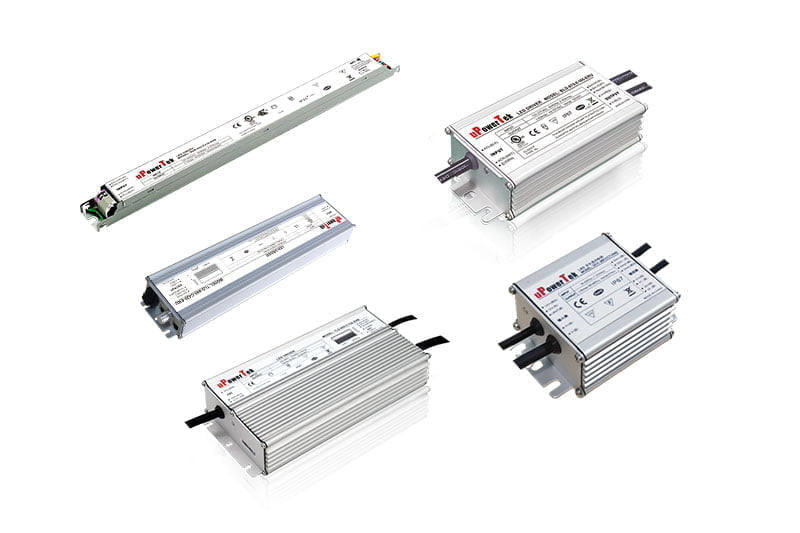
e. LED Driver Form factor
There are different shapes of LED drivers and the form factor is especially important when LED drivers are fixed inside the luminaire.
f. Environment level
For most of the indoor application luminaires, 0-40C ambient temperature operating range is enough. For the outdoor LED drivers, -40-+70C ambient is preferred. For special applications like steelworks, the LED Driver should be able to work at 80C ambient while for the street light in some cold areas like Siberia and Alaska, the LED Driver should be able to start at the temperature of -55C. uPowerTek BLD series are able to meet those tough conditions.


4. How to Find a Better LED Driver
There are a lot of factors that make us be able to discriminate between a high-quality LED driver and common products. Understanding those factors can help a light designer a lot to win the market.
a. LED Driver Efficiency
Higher efficiency not only improves the whole light efficacy but also makes the LED Driver generate less heat thus having a better lifetime. In the LED era, efficiency is more and more important for saving more energy. Currently, the highest efficiency level in the LED driver industry is 96% that uPowerTek BLD-800 and TLD-800 series have achieved.

We also have another article to introduce what is efficiency, you can read if you would like to know more.
b. LED Driver PF and THD
Like efficiency, PF (Power Factor) and THD (Total Harmonic Distortion) are also the concepts that describe the energy converting efficiency and the difference is that Efficiency refers to the energy converting capability from LED driver input to output, while PF and THD refer to the energy converting from power grid to LED driver input. Higher PF (>0.9 according to DLC) and less THD (<20% according to DLC) are always preferred for a high-quality design. (DLC is Design Lights Consortium, a regional group that focuses on energy efficiency specifically in the lighting industry. It is a part of the Northeast Energy Efficiency Partnerships and was originally focused on the Northeast and Mid-Atlantic areas of the United States)


c. LED Driver Inrush current
Almost all of the luminaires are installed together with MCB (miniature circuit breaker) for safety consideration. And if there are multiple LED drivers connected with a single MCB and the overall LED driver inrush current can possibly trigger the MCB so as to result in startup failure. The inrush current issue first appeared when electrical ballast was widely used since either ballast or LED Driver are capacitive devices with big bulk electrolytic capacitor inside generating high peak inrush current during the AC power on. The most popular standard regulating the inrush current is NEMA410 which defines the concept and limits of inrush current.

But the limit in the NEMA410 standard is still not enough when tens of lights or even hundreds of lights are paralleled such as the application of grow lights. And there are a lot of ways to limit the inrush current such as using a soft start circuit and using the current limiting resistor inside LED drivers thus the low inrush current LED driver cost is a little bit higher. Now more and more standard LED drivers offer the feature of low inrush current without adding extra cost.
d. LED Driver Surge protection
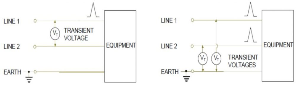
Due to the more complicated electrical design, LED Driver is more susceptible to surge compared with magnetic ballasts. There are 2 major standards regulating the surge protection level of LED drivers, IEC61000-4-5 (Testing and measurement techniques – Surge immunity test) and IEEE Std C62.41.2 (IEEE Recommended Practice on Characterization of Surges in Low-Voltage (1000 V and Less) AC Power Circuit). LED Driver should be heavily protected especially in the outdoor usage by special surge protection circuitry composed by MOV (metal oxide varistor) and GDT (gas discharge tube). And the surge usually comes from two ways: one is high power machine nearby on and off operation, or heavy load-light load sudden switches which lead to surges between line and neutral, which is named as differential mode surge; and the other is from the lightning which makes earth voltage level fluctuate greatly thus creates the surge between either line or neutral and earth, which is named as common mode surge.
The most commonly adopted specification for outdoor LED driver surge level is 6kV for differential mode and 10kV for common mode, according to the test standard of IEC61000-4-5. Generally speaking, the surge protection level is essential to ensure the long term operation of outdoor luminaires thus the designers have to pay great attention to this parameter.
e. LED Driver Output ripple and flickering
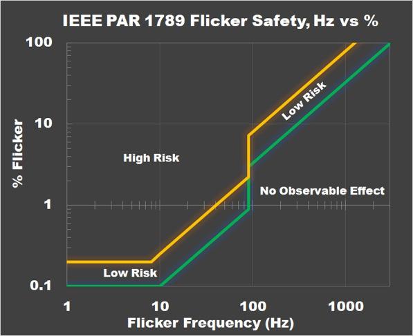
Output ripple is related to the stability and quality of the LED Driver. Lower output ripple means less flickering of LED according to the curve below.


It shows that the LED lumen output is generally quite proportional to LED current, thus lower current ripple can result in lower flickering which is essential for indoor applications which only allow <=5% flickering in most of the countries in the world. There is only one exception that output current can be high even 100%, which is PWM dimming with adequate frequency. The curve below shows that only if the frequency is higher than 1.25kHz, the light can be regarded as flicker-free.
f. LED Driver Line and load regulation
This is a key concept for all the switching power supply including LED drivers. Line regulation describes the output stability versus input voltage while load regulation shows the output stability versus load. The high-quality LED driver can always control the line and load regulation to <=1% value.
g. Programmability of LED Driver
This function is one of the key features the LED lighting era brought because of the too many combinations of LED chips for different design purposes. The ability to adjust the output current is a key demand for LED drivers. In the early stage, a pot-meter was used for adjusting but gradually users found the small device is not reliable and low IP rated. Then programming by infrared controller appeared for a very short period of time because the LED drivers has to be powered on when doing the programming. And from the year 2015, cable programming without powering the LED Driver became the mainstream way to program and the drawback of using the extra cable and doing extra wiring was overcome by NFC programming which is employed by Signify and uPowerTek.
There are quite a few extra programmable functions that can be added to LED Drivers such as time dimming, constant lumen output (lumen decay compensation) and luminaire over-temperature protection which is described below.
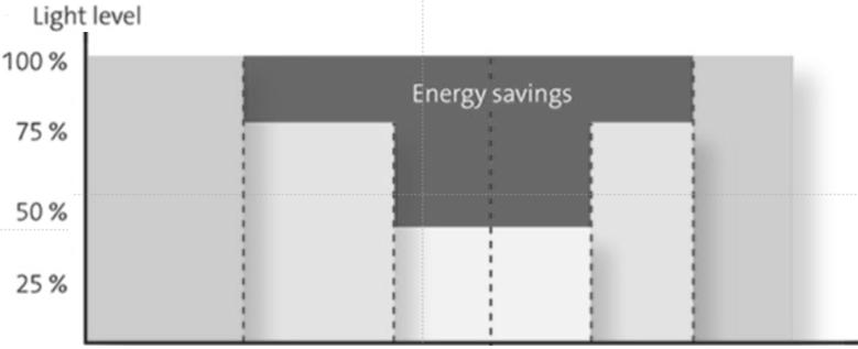
1) Time dimming
This is frequently adopted in street lights as the most convenient way to realize smart control and energy saving.
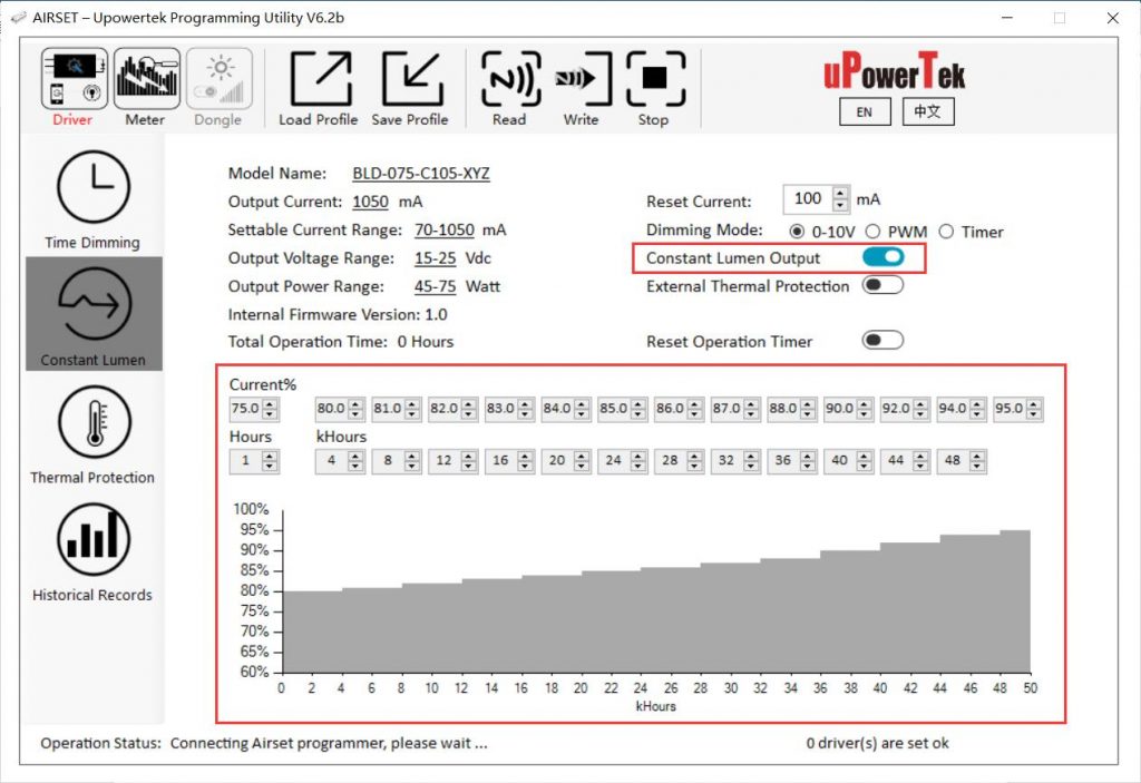
2) CLO (constant lumen output)
The LED light efficacy decreases with the operation time, designers want to keep the light output constant for their luminaires thus the output current of the LED Driver has to be increased accordingly to overcome the decrease.

Through the PC interface, users can set the customized compensation curve according to the LED lumen decay characteristics.
Want to know more about CLO, please check this article. What is CLO in lighting?
3) Thermal protection by NTC thermistor
Many quality-oriented designs have luminaire temperature sensing function so has to protect the product from being too hot or even damaged. So the LED drivers decrease the output current once the NTC (negative temperature coefficient) thermistor which carries the temperature information gets to a certain value indicating the overheating.

Through the programming interface, users can set the thermal foldback resistance threshold and protect the status current value.

h. Tc, max case temperature of LED Driver
This is marked on the LED driver label usually to indicate the hottest point on the LED driver surface.

The definition according to the lamp control gear standard IEC 61347 is: “highest permissible temperature which may occur on the outer surface (at the indicated place, if marked) under normal conditions and at the rated voltage or the maximum of the rated voltage range”. According to LED driver standards either UL or IEC system, the maximum case temperature should not exceed 90C. Tc is one of the key parameters fixtures designers have to check carefully because it relates to reliability and life greatly.

Higher Tc means better thermal performance and higher endurance to high ambient temperature. Though Ta (ambient temperature) rating is always shown in the LED driver datasheet, Ta is not that important compared with the Tc range because the case is much closer to the LED driver internal components compared with air thus reflecting the real operation situation of the LED drivers. In the uPowerTek datasheet, the Ta range is even not shown.

Want to learn more about what is a programmable LED driver, please read this article.
i. Standby power of LED Driver
Now more and more LED drivers support dim to off function to make the whole light go into standby mode. Both Energy Star from North America and ErP from Europe regulate that the standby power loss should be less than 0.5W. The standby power is usually composed of 2 parts, one is the energy from the AC side to keep the LED driver control circuitry still alive to receive the wakeup signal from the controller, and the other is the 12V auxiliary power which is powering the external controller. uPowerTek LED drivers to comply with Directive 2009/125/EC, the requirements of Commission Regulation (EU) 2019/2020 (known as single lighting regulation) effective on September 1st, 2021.
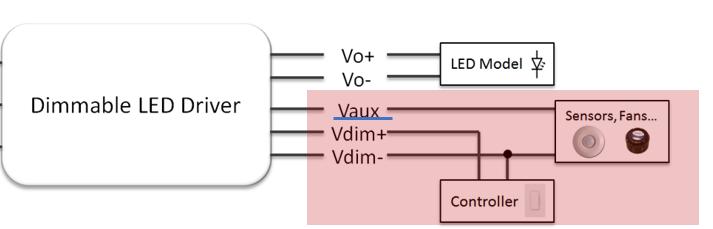
j. LED Driver 12V or 24V auxiliary power
There are a lot of luminaires integrated controllers or sensors so as to provide smart systems or functions to the end-users and the 12V/2~4W power from LED Driver can make the design much easier compared with using an AC adapter to create the 12V. Also, the 12V from LED Driver is safer and more reliable compared to a common adapter thanks to the high internal built-in surge protection circuitry. 24V power is proposed by DiiA and utilized for powering D4i devices like sensors, and the D4i standard is more and more popular with Signify and Osram strong promotion.
k. LED Driver Lifetime and MTBF
It is important to understand that product lifetime and product reliability are two very different, though not unrelated concepts. Unfortunately, because they are both often expressed in hours they are frequently confused. Lifetime refers to the length of time a user can expect a single product to work properly before a known wear-out mechanism renders the product unfit for use. Reliability deals with the random failure rate of a population of products and it may be expressed as a failure rate such as FITs (failures in 109 hours) or as the inverse, MTBF (Mean Time Between Failures). A lifetime of 50,000 hours implies that one would expect any given product to last up to 50,000 hours before failing. An MTBF of 50,000 hours implies that for a population of 1000 units, one could expect to see a random failure every 50 hours (i.e. every 50,000 hours of unit operation). Both concepts are important to understand and manage for a successful implementation of LED lighting.
The typical equation for the life of an electrolytic capacitor takes the following form:
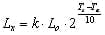
Where,
Lx is the lifetime result,
k is the factor determined by the capacitor’s RMS ripple current and operating voltage, it is provided as either a value or a function,
L0 is the lifetime value tested in the standard condition provided in the datasheet,
Ts is the rated case temperature,
Ta is the operating case temperature.
In general reliability deals with the failure rate of a population of products operating within their rated conditions and within their operational life. A common way of expressing the reliability of a product is a metric known as MTBF. The following equation expresses the very simple concept of MTBF. It is the total operational time in hours of a population of products divided by the number of failures.

The most common method to evaluate MTBF is given by MIL-HDBK-217. And the figure below shows the famous bathtub curve which well illustrates the relation between life and MTBF.

l. LED Driver Certificate
It is important that a high-quality LED driver is certified by 3rd party with a high reputation like UL and TUV. The most essential certificates are UL (North America), ENEC (Europe) and CB (Global other than North America) which can be converted to PSE (Japan), KC (Korea), RCM (Australia), SASO (Mid-east), CCC (China) and etc. We also have another article about global LED Driver certificates, you can read if you want to know more.
5. LED driver manufacturing process
This video is a simple introduction of uPowerTek factory, you can learn the manufacturing process of LED drivers and how we control the quality
6. Summary
LED Driver is the key part working as the heart for lighting fixtures thus it is important that users should choose a suitable and reliable product. We have to consider a balance among the factors like performance, functions, form factors, certificates, price and lead time to the market. So it is not an easy job to find a LED driver or design it well into the light fixture. We are ready to help the designers out from solving the LED Driver related issues and optimize the cost for the whole luminaire design.

Author: George Mao
Mr. George Mao is the founder of uPowerTek company which was started in 2016 and he has been dedicated in the power supply industry for over 20 years and lighting industry for 12 years. He got the EE Master degree in Zhejiang University and worked as a marketing and sales department leader in multiple public companies like MPS, Belfuse and Inventronics. He owns more than 10 invention patents in China. He is now working as CEO and major product manager in uPowerTek and he believes that innovation and quality are the keys for the future of uPowerTek as the global leading LED driver manufacturer.
Have any other questions about LED drivers? Don’t worry, we have a professional team to answer all of your questions, just send us a message here.