Pulse width modulation is a central concept when it comes to the dimming of LED fixtures. But, of course, one marketable trigger of LED drivers is their ability to save energy and cost, and a dimming feature helps achieve this feat. So, combining both concepts triggers the question,” What is PWM Dimming for LED drivers.”
Pulse width modulation(PWM) dimming for an LED driver involves applying the pulse width modulation mechanism in making a LED driver dimmable.
You have everything to gain in this post, as we will cover every crucial aspect involving PWM dimming for the LED driver. In the end, you will feel like a bank of knowledge.
Download this page as a PDF
To save you time, we have also prepared a PDF version containing all the contents of this page, only leave your email and you will get the download link immediately.
An Insight on Dimming
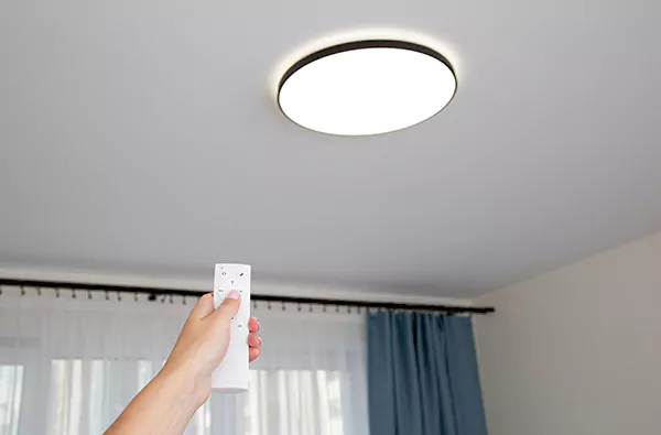
Before we dive into PWM dimming, don’t you think we should touch some basics? To do that, let’s start with what dimming means.
Dimming is the reduction in output of a lighting fixture.
Dimming LEDs possess drivers that perform a dual function, which are;
- Acting as a driver to convert input from the mains into low outputs
- Acting as a dimmer to reduce the amount of energy entering the LEDs
Hence, a dimming feature is vital in LED drivers because it can save energy and power cost.
There are primarily two methods for dimming an LED driver: constant current reduction (CCR) and pulse width modulation(PWM). Let’s see what they entail.
Constant Current Reduction(CCR)
The constant current reduction(CCR) mechanism also goes by the name “analog dimming. “The mechanism follows the relationship that the current moving through the LED is proportional to the output. Hence the system involves reducing the current, which in turn reduces the brightness of the LED.
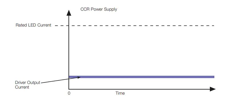
The constant current reduction has its application in the following areas.
- Situations where the drivers are far away from the power source
- Damp areas and outdoor applications
- Areas of strict electromagnetic interference(EMI) standards
Pulse Width Modulation (PWM)
It reduces the mean power supplied by an electrical signal by splitting it into different parts. Pulse width modulation(PWM) applies the principle of rapidly switching between load and source, i.e., turning on and off.
Pulse width modulation(PWM) has its application in the following areas.
- LED driver dimming
- Solar panels
- Motors
What is PWM Dimming
It’s time we go beyond the basics and take a deeper dive into pulse width modulation(PWM) dimming.
Still referencing the basics discussed above;
Pulse width modulation (PWM) dimming is adjusting the current in LED drivers using the PWM technique or mechanism. Hence the LED driver becomes dimmable.
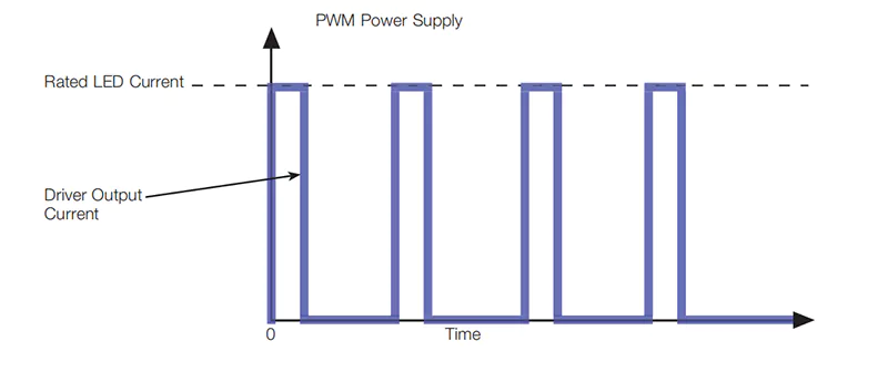
Since every LED has an amount of current needed to get maximum output(rated current), PWM switches the current at a high frequency, which is between 0 and the rated current. The action triggers a ratio of on-time to off-time, which regulates the LED brightness. That explains the pulse width modulation technique.
See the image below:
PWM as A Dimming Signal
Let’s build on the preliminary information we have on pulse width modulation. Now we want to see the PWM as a signal.
Pulse width modulation signals(PWM) are trains of pulses in the form of square waves. For each signal, there exist a high and low point of the wave. The length of time which the signal stays high is the on-time, while the length of time it stays low is the off-time.
Duty Cycle
In the concept of dimming, there is a measure of time the signal can remain high, and we call that the duty cycle. So, for example, if the signal is constantly on, it is a 100% duty cycle. We can control the on-time of PWM signal. For instance, setting the PWM duty cycle to 50%, the signal operates 50% on-time and 50% off-time.
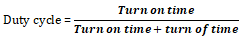
Here is an image for a better

It’s ideal to note that the duty cycle can vary from 0% to 100%, for example, 25% duty cycle, 75% duty cycle, etc.
Frequency
Another integral aspect of the pulse width modulation(PWM) signal is its frequency. The PWM frequency stipulates how fast the PWM signal completes a period, where the period is the time taken for the signal to go on and off.
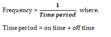
Reconciling the duty cycle and frequency of the PWM signal creates the possibility of a dimmable LED driver.
PWM as LED Driver Output
Pulse width modulation as LED driver output happens when the PWM signal converts to a DC voltage which drives the LED current. The PWM output circuit chops the DC LED currents in a high frequency between the on and off state. Hence the human eye cannot notice the flicker resulting in a change of the LED light output.
We can represent the difference between PWM signal, PWM output, and CCR output in one picture.
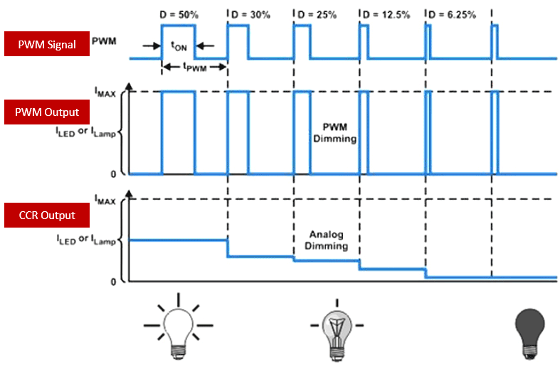
Commonly, people mix up a few things regarding the differences between PWM dimming signal and PWM output. Therefore, we should note a few things below.
The mechanism generates a PWM signal as a digital signal, making it consistent on the dimmable cable. On the other hand, the driver detects the PWM duty cycle to determine the output current.
Realizing PWM Dimming Drivers in the Market
It’s evident how PWM dimming drivers continue to gain relevance in LED lighting. But it is best to know that there are two methods to realize PWM dimming drivers. So let’s see what they are.
Fake PWM Dimming
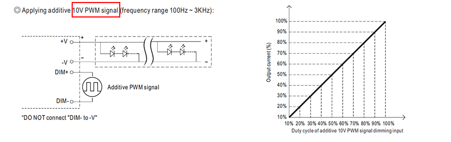
The fake dimming method is a concept that converts the PWM inputs into an analog control signal. There is a resistor-capacitor(RC) filter inside the driver.
The RC filters the PWM signal into DC voltage proportional to the duty cycle. One advantage of fake PWM dimming is that it is noise-free. It is noise-free since the LED current is constantly continuous at the output.
On the other hand, the drawback with this method is that the peak value of the PWM must be 10V; otherwise, the accuracy is terrible. In addition, the resistor-capacitor(RC) parameter limits the frequency of the PWM signal.

Want to read it later?
To save you time, we have also prepared a PDF version containing all the contents of this page, only leave your email and you will get the download link immediately.
Real PWM Dimming
In the real PWM dimming, the LED currents turn on and off at the designated frequency and duty cycle. There is a microcontroller(MCU) inside the driver. The presence of the MCU enables the PWM signal to detect peak voltages. Real PWM dimming allows a broader range of PWM frequency.
A significant positive with the real PWM dimming is its ability to preserve the white point of the LED output. It also permits a high level of the reference voltage, which is above offset errors. All uPowerTek drivers integrate MCU to work with PWM dimming.
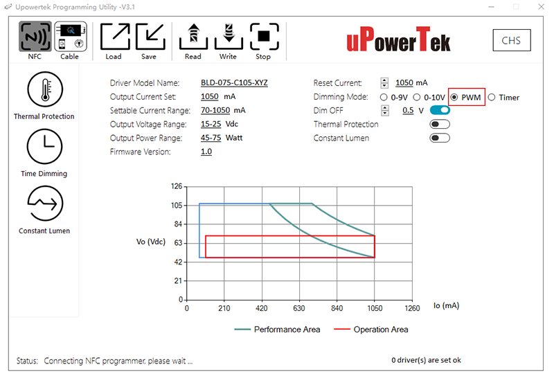
Users need to choose PWM dimming mode in the driver programming software.
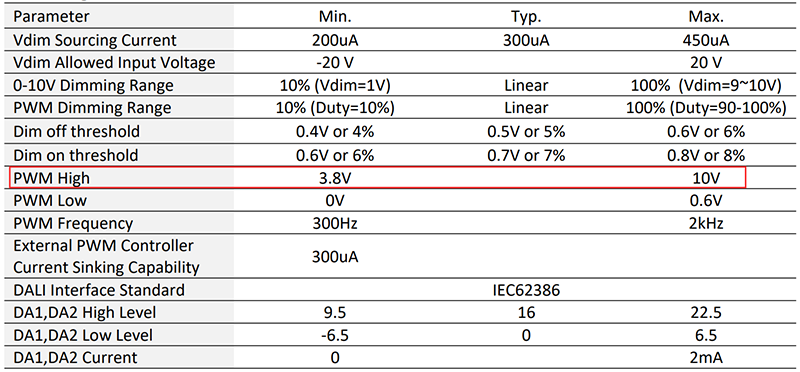
This table is from uPowerTek LED driver datasheet, we can see that the PWM dimming signal allows very wide voltage, from 3.8V to 10V. It means that uPowerTek PWM dimmable LED driver is not limited to 10V only PWM signal, it can accept any voltage between 3.8V and 10V, such as 5V PWM dimming signal. Because uPowerTek LED driver has the real PWM dimming function.
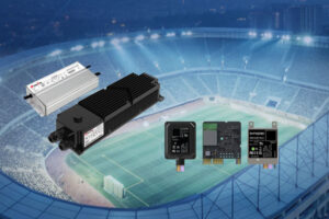
uPowerTek: A Reliable Provider of PWM LED Dimming Driver
uPowerTek is a renowned and trusted manufacturer of dimmable LED drivers. With an increasing reputation, highly experienced workforce, and updated methods, uPowerTek provides the best dimmable LED drivers.
We provide;
- Constant current dimmable LED drivers with CCR output
- Constant voltage dimmable LED drivers with PWM output
Constant current dimmable
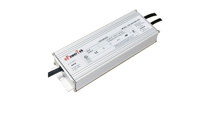
- Constant Current Output from 60Watt to 800Watt
- IP67 Waterproof for outdoor lighting and horticulture lighting
- Supply Voltage: 90-305Vac or 127-420Vdc, 380Vac for 2 hours
- Great Surge Immunity 10kV
- -55℃Cold Ambient Startup (Optional)
- 100,000Hour Life @ Tc=75℃ & 7 Year Warranty @ Tc<=75℃
- AirsetTM NFC Programmability
- ENEC/CB/CCC SELV Output
- Safety according to EN 61347-1, 61347-2-3, 61347-2-13, 62384
Constant voltage dimmable
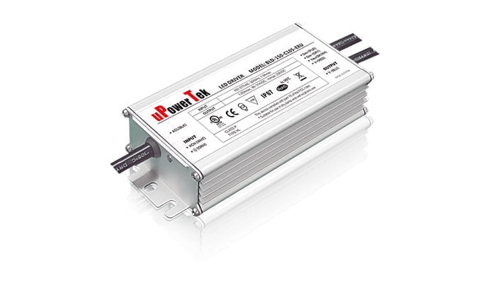
- 12V, 24V, 48V constant voltage output for LED strips
- Supply Voltage: 90-305Vac or 127-420Vdc, 380Vac for 2 hours
- Great Surge Immunity 10kV
- PWM Output Frequency >4kHz
- 100,000Hour Life @ Tc=75℃
- 7 Year Warranty @ Tc<=75℃
- 0-10V/PWM/DALI /Push (Switch) Dimmable
- Dim Off with 0.5W Standby
- Safety according to EN 61347-1, 61347-2-3, 61347-2-13, 62384
All our LED drivers, irrespective of constant current or constant voltage, all support PWM dimming signal.