DALI is a very popular dimming and control technology in the world, but there are two many concepts and new technologies in recent years, so we write this article to help you understand the DALI dimming technology and help you to be a DALI expert, we believe it will help your work, keep reading.
1 DALI Alliance Introduction
1.1 DALI Alliance
DALI Alliance, the Digital Illumination Interface Alliance (DiiA), is an open global intelligent lighting manufacturer alliance. It aims to achieve a unified international standardized agreement to achieve digital communication in the smart lighting system by promoting the application of digital addressable lighting interface (DALI) technology.
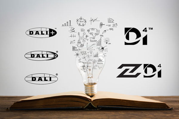
DALI is an open, unified, and compatible intelligent lighting control protocol based on the international IEC62386 standards. It is uniformly formulated by the DALI Alliance and applied globally. After years of development, the DALI Alliance has expanded the DALI protocol and introduced certification plans, including releasing standards such as DALI-2, D4i and DALI+. The products certified by DALI-2 can be compatible with interoperability, and realize the intelligent and efficient control of the lighting system, including precise lighting, coloring temperature, color adjustment, supporting sensors, switch panels, and other devices. In particular, the asset data of the lamps, the operation and energy efficiency data are monitored and collected, and the analysis and diagnosis are also supported. It also supports emergency lighting spontaneous automatic functions. DALI intelligent lighting system can access the building’s automated control system or IoT system to interconnect with other building systems and innovative city systems.
1.2 DALI Alliance Member
1.2.1 Member overview
As of July 2022, the DALI Alliance has 313 members worldwide, including 33 conventional members, 238 ordinary members, and 42 communications members. They are all top manufacturers from the lighting industry. After becoming a member of the DALI Alliance, they can use DALI-related trademarks on certified products. The full list of members can be available on the following website to view: www.DALI-alliance.org/membership/member-companies.html
1.2.2 DALI Alliance member level and rights
The DALI Alliance is an open global lighting company alliance. Members are divided into three categories— Regular Members, Associate Members, and Community Members.
As shown in the table below.
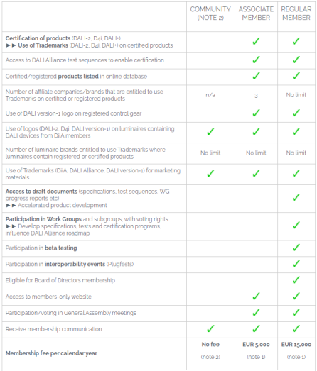
A more detailed list of equity can be accessing the following URL:
https://www.DALI-alliance.org/membership/benefits.html
1.2.3 Join DALI Alliance process

Enterprises can apply to become members of the DALI Alliance. The steps for entering the meeting are as follows:
- The first step: visit https://www.DALI-alliance.org/membership/how–join.html, know and agree to DALI Charter
- Step 2: Download DALI Alliance Member Application Form
-Lighting company download registry COMMUNITY MEMBER Registration Agreement
-Application Form for Full Members and Ordinary Memberships
- Step 3: Fill in, and send the registry or application form: admin@DALI-alliance.org
- The fourth step: The DALI Alliance will notify the members after completing the review. For full-time members and ordinary members, pay the membership fee, and the lamp communication members do not need to pay.
- Step 5: Provide corporate logo, and DALI Alliance website to display member information.
See the link for the steps of the membership application:
https://www.DALI-alliance.org/membership/how-to-join.html
1.3 DALI standard
1.3.1 IEC 62386 series standard
DALI is an industry standardization agreement, specified explicitly in the international standard IEC62386 and the new DALI new specification by DIIA.
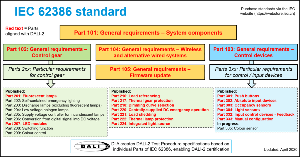
IEC TC34’s WG11 is responsible for writing and maintaining the IEC 62386 series standards. The DALI Alliance is an active participant in TC34/WG11. “IEC62386-Digital Disable Lighting Interface” can be purchased on the IEC website. The figure below shows the IEC 62386 standard series.
1.3.2 DIIA specification
DIIA expands the new features of DALI, defines the additional DALI features and functions, and develops into DIIA specifications; DIIA transfers it to IEC as a new part of IEC 62386.
DIIA specifications are provided to everyone for free, including DALI Alliance members and non-members, download address:
https://www.DALI-alliance.org/specifications/download.html
1.4 DALI product registration and certification
1.4.1 DALI-1 registration

DALI 1 Products only comply with self-state and registration for some DALI control devices. Registration is not charged unless the DALI Alliance is specially requested; there is no need to submit the test results for inspection. However, essential inspections will be performed for product information (GTIN, product name, test sequence version and IEC standard number).
All control devices with DALI 1 trademark and DALI-1 sold in the market must be registered on the DALI Alliance website.
Currently, DALI-1 products have stopped registration.
1.4.2 DALI-2 registration
The DALI-2 certification plan is based on DALI IEC62386 and standard DIIA specifications. It includes more functions, equipment types, and comprehensive test requirements, and the old DALI system is backward. Support all equipment of the lighting control system: driving power, input device (such as sensors, switches), application controllers (such as DALI control device) and DALI bus power. The biggest highlight of DALI-2 is to ensure compatibility and interconnection through authentication rather than self-state and fill the gap of the original DALI-1. Its launch is very successful, and the DALI Alliance has certified over 2,000 smart lighting control products from various member companies worldwide.
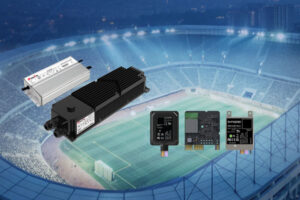
1.4.3 D4i and ZHAGA D4i

D4i is a DALI-2 function extension. It is an extension of the DALI-2 certification. It aims to increase support for data-related functions, including lighting assets, energy and operation based on the intelligent IoT lamps and DALI-2 lighting control. Collection and analysis of data such as diagnosis. For the DALI-2 control devices and smart lamps, DALI Alliance cooperates with Zhaga Alliance and launches a joint certification plan Zhaga-D4i.

DALI-2 control device (controller or sensor) requires a Zhaga connector plug, and the software protocol meets the D4i standard. Smart lamps use D4i certified power supply and have a connecter socket required by Zhaga. A single lamp controller can give the lights with the ability of “IoT Ready” to deploy the intelligent lighting control system quickly.
1.4.4 DALI+
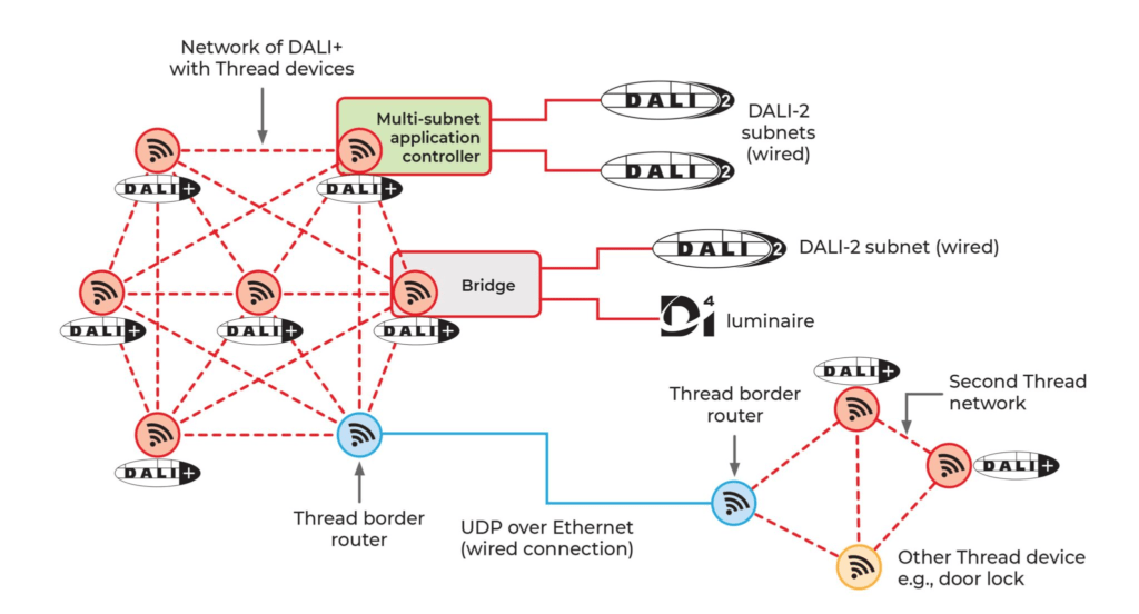
DALI+ is the latest certification brand launched by the DALI Alliance. DALI+ supports the existing DALI commands based on wireless or IP networks based on wireless or IP networks. However, these commands are transmitted through wireless and/or IP-based media instead of DALI-2 communication cable. DALI Alliance will use Thread as its first wireless IP connection technology for DALI+. The DALI+ certification requirement is under development. In addition, for the support of DALI on the wireless network, the DALI Alliance also released the gateway specifications between DALI and Bluetooth, DALI and ZigBee. Wired DALI-2 or D4i lamps can be integrated into the wireless ecosystem of Bluetooth or ZigBee. In subsequent chapters, specific technical details about DALI-2, D4i, DALI+ and wireless gateways will be introduced.
2 DALI Technology Introduction
2.1 DALI technology introduction
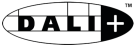
Digital addressable lighting interface, referred to as DALI (Digital Addressable Lighting Interface), is a digital communication technology for lighting control systems. It realizes the two-way communication between the control device (such as the application controller), the input device (such as the switch, the sensor), and the control device (such as the driver’s power, the ballast), to realize the switch, lighting, and color adjustment of the lights (including color and color temperature) and lighting equipment information (manufacturer information, electricity information and operation and maintenance information, etc.). Because it has an unparalleled advantage over other agreements, it has been increasingly widely used in commercial and public lighting fields.
2.2 DALI history
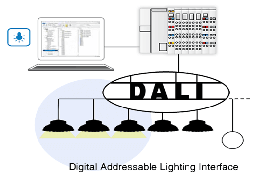
In 1991, the Austrian company Tridonic launched the world’s first digital lighting interface DSI protocol for light signal control for lighting. Its advantage is that the control signal line is not polarized, and the material and specifications of the cable are low. Still, it can only be broadcast without addressing single lights.
In the late 1990 to develop a better digital lighting technology to meet the needs of the lighting market, Tridonic and other well-known Euro well-known equipment manufacturers Helvar, Osram, Philips and other well-known lighting have jointly developed the digital addressable lighting interface protocol (DALI). It has the following advantages: low cost, convenient wiring; can achieve single light control and group control; can return the state data from the control device; support the addition of other devices, etc. Subsequently, the Lantern Branch of the ZVEI (German Electrical Electronics Association) set up DALI Ag (Activity Group) to promote the DALI protocol and related products. DALI AG members mainly came from essential manufacturers in the field of commercial lighting. As DALI applications are becoming more and more extensive, in addition to commercial lighting, in other areas of lighting (such as public lighting, home lighting, etc.), they have also been applied, and they accepted IEC 60929 for tube-shaped fluorescent lamps as part of the “Performance Requirement” standard.
Since 2009, DALI is separated from the IEC 60929 standard as an independent IEC 62386 series standard. The DALI standard system is initially established, and registered manufacturers can make DALI trademarks for products that meet the standards. The product does not need to undergo third-party forced certification, as long as it claims to meet the standard requirements, you can hit the DALI trademark. Since 2014, DALI Ag has improved and enhanced the DALI protocol, forming the second edition protocol DALI-2, and the content of the DALI standard system has gradually improved. At the same time, in order to regulate the application of the application-side product market, all products must be tested and recognized in order to hit DALI trademarks.
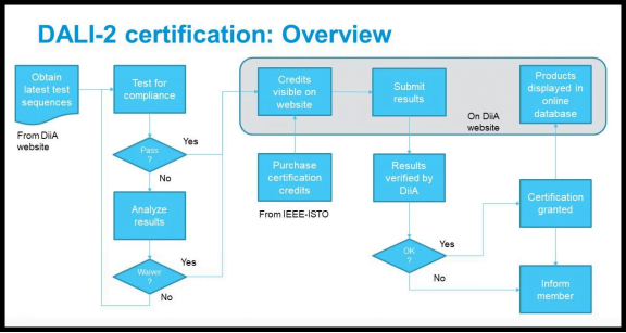
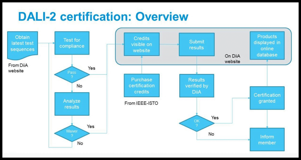
In 2017, DIIA (DIGITAL ILLLUMINATION Interface Alliance, Digital Lighting Interface Alliance) passed the IEEE-ISTO (IEEE Industry and Technology Organization) through ZVEI. The implementation of marketing and product certification. In order to facilitate people’s understanding, starting in October 2020, DIIA announced the marketing work as a brand name “DALI Alliance” (DALI Alliance), and the work development and certification processes are still implemented by DIIA.
With the rapid development of the Internet of Things in recent years, the interconnection of all things will inevitably become the future development trend of intelligent lighting. By connecting with the intelligent street light controller defined with Zhagabook18 or NEMA C136.41, DALI realizes the D4i application of outdoor road scenes, which can obtain lamp information, energy consumption and diagnostic data in real time, including real-time power consumption, failure status and operating time, etc. Essence
For the IoT application of smart buildings, it is achieved by combining Zhaga Book20. In order to integrate with the wireless agreement, the application of DALI wired+wireless in recent years is underway. For example, the system composed of wireless Bluetooth Mesh/ZigBee and wired DALI. Through the DALI wireless gateway, two systems can be achieved, and other devices can be connected without additional wiring.
In 2021, on DALI on the IP network and wireless network, the DALI Alliance also plans to launch DALI+ certification plan. The DALI protocol can not only realize the connection of the lighting system equipment, but also integrate the interconnection with various smart devices by integrating in other systems. For example, the DALI system can access the building management system through the application controller/ Gateway/ Gateway (Gateway), which can realize the interconnection of smart lighting equipment and other smart devices in the building.
From wired DALI to wired+wireless, to wireless DALI, it is step by step to accelerate the IoT empowerment of the intelligent lighting system, thereby providing more possibilities and imagination for lighting.
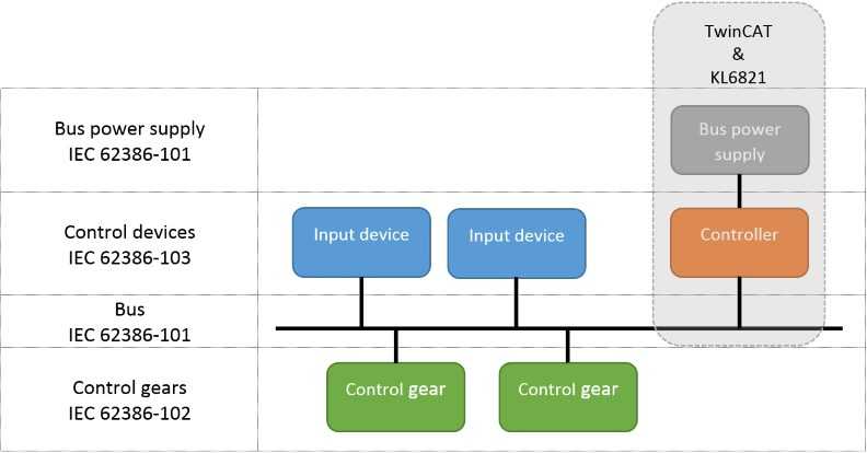
2.3 DALI system architecture and composition
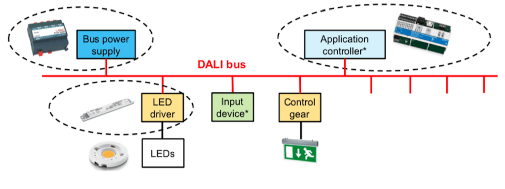
The DALI system consists of bus power (≥1), control device (≥0), input device (≥0), bus (1), and application controller (≥1).The components are introduced below.
2.3.1 Bus power supply
It provides power in the bus. It can be an independent device or integrated into the application controller.
2.3.2 LED driver
Connect to the bus and receive instructions to control the devices that directly or indirectly control the switch/voltage/current output.
2.3.3 Controller or sensor
Equipment connect to the bus and send instructions to other devices (such as control device) on the same bus. It includes the application controller and input device (switch panel, sensor, etc.)
2.3.4 Concentrator or master
The brain of the DALI system is connected to the bus parallel and sent instructions to control the input device or control device on the bus. The concentrator can use a variety of sources of information, including: control device, input device, other application controllers or external devices, bus and systems to control the lighting system. The concentrator is divided into a single-owner application controller or multiple main application controller or their variants.
2.4 DALI system working principle
Action instructions such as the control device (such as DALI host) are accepted and executed by the control device (DALI-driven power supply) through the bus. Send the corresponding information. The sending and receiving of the information should abide by their respective sequential rules, and the bus power supply should be powered on the various equipment interfaces on the bus.
It is worth noting that the system architecture diagram is not static. The system architecture of the multi-main application controller should start the corresponding mechanism to avoid conflict. In addition, the bus power supply and input device can be integrated in the application controller separately, and can also be incorporated in the application controller at the same time. The system architecture diagram also changes.
The communication between the input device and the application controller, between the multi-master application controller, the communication between the application controller and the control device is performed through DALI FF (forward frame) and BF (backward frame) for each in the system each different frames of communication between devices. The communication between the input device and the application controller, the multi-master application controller, the communication between the application controller and the control device are both bi-directional. BF cannot actively send instructions, but can only give back the information when responding to FF.
The DALI system adopts a bi-directional and half-dual-work communication method. The controller uses the controller to send a 2-byte FF to the control device, and the control device returns 1 byte BF status information; 3 bytes of FF instructions, and return 1 byte BF processing information; single owner application controller generally sends a 2-bit FF forward frame, but you can also send a 3-byte forward frame when inquiry input device FF. In the DALI-2 system, the input device cannot directly send instructions to the control device, and the instruction must be sent to the control device through the master. For specific FF and BF frame structures, refer to the IEC 62386-101, 102, 103 standards.
2.5 DALI command
DALI includes three commands: control, configuration and query.
The command can be sent to a single device, a set of equipment or broadcast to all equipment.
2.5.1 Control command:
You can turn on the lights, light up, fade (gradient) and scene control. Scene control allows the entire system to quickly and effectively deploy lighting photos/color temperature/color. Each control device has 16 scenarios. A single “turn to the scene” command indicates that all the lights or lights of all lights or lights are transferred to the illuminance and/or color of color or color/or color of the separate pre-defined.
2.5.2 Configuration command:
You can query the running parameters of the lamp.
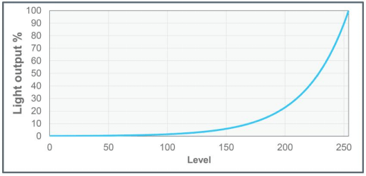
DALI is designed for intelligent lighting. The biggest feature is that it can control the light output accurately, repeated and standardized. The certified DALI-2 control device follows the standardized lighting curve, and its design meets the sensitivity and brightness perception requirements of human visual effects in human work. As shown in the figure below, the precise lighting curve refers to IEC 62386-102, and section 9.3.
2.6 DALI system wiring
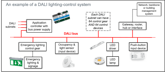
In a single DALI system, a bus can address the number of device no more than 128, that is, 64 control devices and 64 control devices, but it does not mean that only 64 lights can be controlled. According to the output nature of the control device, DALI can be controlled. DALI You can control more than 64 lights. In the system of multiple DALI bus combinations, the number of bus addressing devices is multiple of the number of combinations. DALI system wiring is simple, regardless of positive and negative electrodes, DALI bus is ordinary cable. Considering that the agreement requires the maximum voltage drop between the two devices on the bus of the bus to 2V, the maximum current on the bus does not exceed 250mA, and the two communication units are between The longest distance does not exceed 300m. The table below shows the maximum communication distance allowed by different cross-sections and different wires at 25 ° C.
| Cord Material | Cord Diameter (mm2) | Maximum Distance (m) | Cord Material | Cord Diameter (mm2) | Maximum Distance (m) |
|---|---|---|---|---|---|
| Copper | 0.14 | 31 | Aluminum | 0.14 | 19 |
| Copper | 0.5 | 112 | Aluminum | 0.5 | 68 |
| Copper | 0.75 | 168 | Aluminum | 0.75 | 102 |
| Copper | 1 | 224 | Aluminum | 1 | 136 |
| Copper | 1.5 | 300 | Aluminum | 1.5 | 205 |
| Copper | 2 | 300 | Aluminum | 2 | 273 |
| Copper | 2.5 | 300 | Aluminum | 2.5 | 300 |
2.7 Technical parameters
| Item | Parameter | Description |
|---|---|---|
| Maximum number of short addresses | 64 | bus addressable control devices and control devices |
| Maximum number of group | 16 | The maximum number of grouping of control devices and control devices |
| Maximum number of scenes | 16 | systems defaults to the maximum number of scenes |
| Bus voltage | 12-20.5 VDC | typical value 16 VDC (but not SELV because there is no electrical isolation) |
| Power supply current | 8 mA-250 mA | 8 mA-250 mA considers the line resistance. The maximum current during design is generally calculated at 200 mA |
| Maximum allow voltage drop | 2 VDC | DC bus Between any two nodes of the two nodes drop |
| Data transmission rate | 1200 bps | 1200 BPS speed is slower but stronger anti-interference ability |
| Cable length | ≤300 m | The distance between the two nodes on the most extended two nodes on the bus in the bus |
2.8 DALI system five advantages
DALI is currently widely used in large-scale lighting scenarios, such as shopping malls, hotels, airports, subway stations, villas, roads, etc. In actual engineering applications, compared with other lighting protocols, the DALI system has the following advantages:
2.8.1 Easy to wire
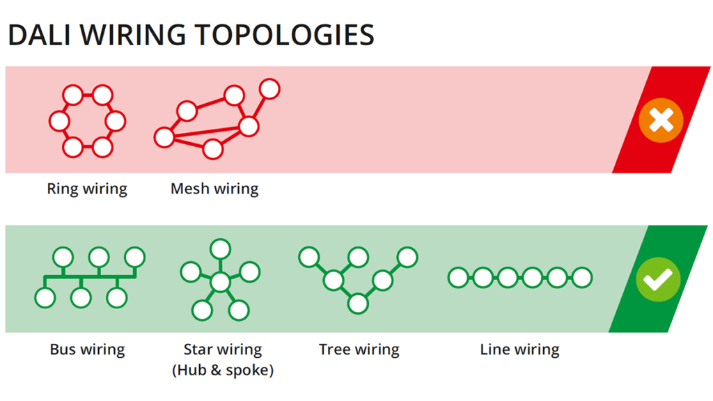
DALI adopts any topological structure except the loop type, the power supply and the control signal are carried by the same cable, and the signal line is not polarized, making it less wiring, simple and convenient. The wire uses 2 cores 1.0mm² ~ 1.5mm² ordinary cable and interface isolation, regardless of positive and negative. It can be wired with 220V, and the wiring requirements are low.
2.8.2 Flexible control
The DALI system can achieve single lights, marshals and broadcast control by controlling control commands. One car circuit is 300 meters, and 64 control devices (sensors, switches, etc.) of 64 control devices in one circuit support scene control, color control, lighting control, lighting control, lighting control, and lighting control, lighting control, lighting control, and lighting control, and lighting control, lighting control, and lighting control. Gradient transition control equipment can be used from the DALI bus and can read the status and information of the device.
2.8.3. Strong compatibility
The official certified equipment provided by different manufacturers can achieve good compatibility and interoperability.
2.8.4. Easy to upgrade
No need to re-wiring. The lighting system can be configured through the software to add operations, modification instructions, and improvement functions.
2.8.5. Integrate DALI system with the BMS system
It can run as an independent system or be integrated into the construction management system (BMS) or smart home system as a lighting subsystem.
3 DALI-2
3.1 DALI-2 history
The DALI protocol has developed since the 1990s. At first, it was used as an alternative to simulation control. Since its launch, it has been widely used in the market. With the development of market applications, the original standards have not been able to cover all application needs and product types. At the same time, because the DALI standard is compliant Caused many compatibility issues. To solve these problems, DALI-2 came into being. DALI-2 is the second version of the DALI protocol standard IEC 62386-DALI 2, referred to as DALI-2, and uses a separate brand trademark.
3.2 The upgrade and new feature of DALI-2 from DALI-1
DALI-only defines the function interface of the control device (control gear, refers to the DALI driving power, ballast, etc.), and the implementation of the control device (controller, control host, switch, sensor, etc.) is generally by manufacturers. According to the interface definition of the control device, a compatibility problem will soon occur, such as the control masters from different manufacturers cannot match the same control power supply. For engineering facilities, it is often strictly locked in specific hosts and power equipment, adding a lot of uncertain risks. To solve these problems, DALI-2 came into being. DALI-2 improves the shortcomings of the DALI-1, and focuses on the functional interface of the control device. At the same time, DALI-2 requires that the products that meet the standards must be compulsory certification, which will greatly improve the various unsatisfactory issues left by history, which is a strong guarantee for the entire DALI ecology.
In detail, DALI-2 has made the next four aspects based on DALI-1:
- Fix the errors and deficiencies in DALI-1, such as more detailed and strict requirements for the timing of transmission, and also remove some unused features.
- Added some new control devices and features to complete the types and characteristics of the new control device, which are achieved through some new command interfaces and transmitted message frames. Specifically includes load reference, thermal protection, load referencing, thermal gear protection, dimming curve selection, demand response, thermal lamp protection, integrated light source, power measurement, bus power and AUX power, asset and diagnostic, centrally-supplied, DC emergency operation, light-output compensation over lifetime, colour Tc and colour xy.
3.3 Mandatory certification
Putting compulsory certification requirements for products that meet the latest standard DALI-2 and formulating a specific method process by the DALI Alliance is critical to the development of standards.
3.4 DALI-2 standards and equipment
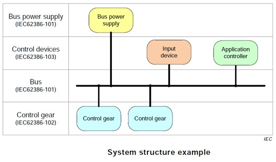
3.4.1 DALI-2 Basic Standards
The common demand standards for the DALI-2 Standard IEC 62386 Agreement Club are as follows: as follows:
- IEC 62386-101 (part 101): General Requirements-System Components
- IEC 62386-102 (part 102): General Requirements-Control Gear
- IEC 62386-103 (part 103): General Requirements-Control Devices
The PART 101 is the basis of the entire DALI protocol, which is standardized from the perspective of the DALI system. Part 102 conducts general specifications for the control gear in the DALI system, and publishes the PART 2xx series standard files for different product types to specially standardize. There is no clear definition of control device in DALI-1. DALI-2 formulates the standards of the PART 103 and Part 3xx series standards for general device and special expansion needs.
3.4.2 Control Gear
The PART 102 standard makes detailed regulations on electrical specifications, transmission protocols, operation methods, variable meaning, command definition and test processes that all control gear needs to meet, and specify the control gear. The specifications are specified separately. In actual use, how can the host in the system know what type of control gear on the bus? At this time, a device type is used to identify. Different device type represents different types of control gear and the expansion characteristics of this control gear. Different standards part 2xx describe the special needs of each different Device Type, so a control table is generated, namely the part 2xx-device type number.
Control gear’s standard Part 2xx and Device Type Number are shown in the table below. When the DALI device type (DT) list is developed, the device type no longer identifies the specific control device type according to the literal sign, but is more like a feature set. Because although part 102 pulls out the common needs of all types of control gear, there will be some different device type control gears in practice. The DALI-2 standard classifies the characteristics of the original DT0 ~ DT9 control gear. The new device type is shown below in PART 216 and later standards.
| Part | Device Type Number | Type Of control gear |
|---|---|---|
| 201 | Fluorescent lamp control gear | Device Type 0(DTO) |
| 202 | Self-contained emergency control gear | Device Type 1(DT1) |
| 203 | Discharge(HlD)lamp control gear | Device Type 2(DT2) |
| 204 | Low-voltage halogen lamp control gear | Device Type 3(DT3) |
| 205 | Incandescent lamp dimmer | Device Type 4(DT4) |
| 206 | Conversion to D.C.voltage(1-10V,0-10V converter)1-10V/0-10V | Device Type 5(DT5) |
| 207 | LED lamp control gear LED | Device Type 6(DT6) |
| 208 | Switching(relay) control gear | Device Type 7(DT7) |
| 209 | Colour control gear | Device Type 8(DT8) |
| 221 | Demand response | Device Type 20(DT20) |
| 222 | Thermal lamp protection | Device Type 21(DT21) |
| 223 | Light-output compensation over lifetime | Device Type 22(DT22) |
| 224 | Integrated light source | Device Type 23(DT23) |
| 225 | Colour Tc | Device Type 24(DT24) |
| 226 | Colour xy | Device Type 25(DT25) |
3.5 Common device type DT (DT1, DT5, DT6, DT8)
3.5.1 DT1 Self-contained Emergency Lighting Control Device
The type of control device is mainly divided according to the type of light source and the purpose of the device. It can be seen from the Part 2xx-Device Type number that part 202 describes self-containing emergency lighting control. DALI emergency lighting system aims to meet the requirements of key emergency lighting standards, such as IEC 62034: 2012 “Battery Power Supply Escape Lighting Automatic Test System”. One key feature is the ability to perform functional test-this is a weekly or monthly test to ensure that emergency lamps still exist and run normally. It also includes duration testing to confirm that the emergency light can use the battery power supply within the required time (usually three hours).
DALI system to control the benefits of emergency lighting have begun from the beginning of installation. Using the DALI emergency system with the DALI control system for general lighting can reduce the required wiring volume and cost of the early stage. In the long run, this also makes the system easier to operate and maintain, more cost-effective. Conventional lighting and emergency lighting can be managed and monitored together, and any changes to the system in the future will be as simple as possible.
DALI core wired infrastructure brings strong solutions, and DALI emergency systems can also be combined with wireless or cloud-based control systems. DALI League (DIIA) members also allow users to remotely debug and manage emergency lighting systems through user-friendly interfaces. For example, customers can remotely check the performance of a single accessory, analyze the data to optimize the battery life, and reduce the stoppage time by analyzing the analysis. Many tragedies in reality remind us why emergency lighting is so important. Even if no one is hurt, buildings without compliance emergency lighting may be closed, and the person in charge may face prosecution. People are more concerned about the high standards set by the emergency lighting system at any time to ensure that it has settled for it, which is why the DALI emergency lighting system is constantly developing. In the final analysis, emergency lighting is to save life, so its reliability is crucial.
DALI defines four types of self-contained: A, B, C, or D, and the control device can only be one of these types.
- Type A: When the AC power exists, the light can be dimmed or turned off, but when the AC power supply does not exist, the light is on
- Type B: When the AC power exists, the light can be turned on or turned off, not dimmable, but when the AC power supply does not exist, the light is on
- Type C: Regardless of whether the AC power exists, the lights are always there
- Type D: Only when the AC power does not exist (or in the test mode, the light lights up
3.5.2 DT5-DC voltage (0/1-10V) converter
The DT5 control device is specified in part 206. The DT5 is to support the control device of the traditional simulation lighting interface (0/1-10V) into the DALI system. In the DALI project application, sometimes it is impossible to select the control device that directly supports the DALI control interface, or it must be integrated with a part of the existing simulation lighting system, or in order to reduce the application needs and construction costs, it requires intermediate devices to achieve conversion and docking of DALI bus. The DT5 is born for this. After receiving the DALI control device that supports DT5, the lighting illuminance level is converted into a set of simulation lighting output signals to the access to LED driver analog output.
3.5.3 DT6-LED Driver or control gear
Part 207 describes the characteristic requirements of the control gear, a device type 6. For the convenience of the name, the Device Type 6 is abbreviated as DT6, so the DT6 is DALI Dimmable LED DRIVER. From the DALI standard organizational structure, it is easy to see that the control devices of DT6 must meet the three standard specifications of Part 101, Part 102 and Part 207. The DT6 is currently the largest DALI product type in the market. The main product forms are LED drivers with constant current and constant voltage, which are widely used in outdoor and indoor lighting control systems.
3.5.4 DT8-Color Control Device
DT8 is the abbreviation of Device Type 8 (color control device). However, unlike DT6, the type name of the DT8 does not look like a specific lamp control device, nor does it like the Device Type 7 (switch control device) to correspond to a specific product. In the part 209, it only mentioned that its definition object is a control device that can change the output color. It may be the LED lamp control device, or it may be the control device of other types of light source lamps. Only the development of lighting technology to this day, in most cases, the control device that supports DT8 is actually the LED lamps control device that supports light output color. Furthermore, DT8 refers to the DALI tunable white LED driver or multiple output LED driver. From the perspective of actual application requirements, DT8 control gears must meet the three standard specifications: Part 101, Part 102 and Part 209.
Before the standard formulation of the DT8, if the light color needs to be adjusted in the application, the general approach is to use the two DT6 devices to connect CW (cold white) and WW (warm white) two different color temperature sources of different color temperatures, and then adjust the two-way control device output level through the master, so the color temperature and brightness can be changed.
If you want to adjust the RGB color temperature, you need more DT6 devices to connect different colors of light sources of different colors. From the results of the adjustment, only DT6 can also achieve the purpose of adjusting the color temperature or RGB color of the lamp. However, the disadvantage of this method is also obvious:
- You need to have two or more control devices/addresses on the bus
- The adjustment characteristics of color temperature or RGB color are all completed on the side of the master controllers, and it is difficult to guarantee consistency and compatibility
- Using multiple independent control devices to increase the cost and complexity of the system. It also requires more installation space. To comply with the DT8 standard control device and only one address is occupied, the characteristics of the color adjustment are integrated to the internal, so it can solve the above problems well, and it is easier to use.
The content of the DT6 and DT8 specifications will be greatly reduced until the protocol version is updated until gradually abolished, because the new device type DT24 (Tc) and DT25 (xy) can be combined to replace it.
3.6 Input device
Because all control device specifications (including part 103 and part 3xx) are proposed by DALI-2, they also use the same idea as control gear, just to distinguish different names. control gear uses only one Device Type, which is easy to cause confusion. Control device uses Instance Type and Feature Type to represent specific types and abstract characteristic types.
- Instance Type, indicating the input device type, the range of the value is 0 ~ 31, Instance Type 0 is specified in part103, Instance Type 1 ~ 31 specifies in part 301 ~ 331 specifications
- Feature Type represents the characteristic type of extension, with a value range of 32 ~ 96, and regulates in the PART 332 ~ 396 standard
3.7 DALI-2 device Firmware update
One of the major features of the Internet of Things era is change. With the improvement of the use scenarios and user needs, if the product can be upgraded to the function after the factory is installed and deployed, it will be an attractive value-added point. In consumer smart hardware products such as smartphones, this is usually called OTA (on-the-air) update because it is generally received through wireless communication and upgrades. In addition to the equipment with firmware upgrade capabilities showing the products to users, they can still add new functions and repair the known error vulnerabilities after installation. For manufacturers, they can also achieve rapid iteration of the product. In other words, manufacturers do not have to follow the lengthy development and manufacturing processes of traditional hardware products. Instead, they can learn from the software industry. After defining the main needs and completing the main functions, they can push the product to the market.
The part 105 in the DALI standard defines the standard firmware update transmission mechanism for the control device, and uses 32-bit forward frame to transmit updated firmware image. There is still the opportunity to achieve firmware update through the DALI bus itself without removing it. However, it should be noted that firmware updates need to be supported by the updated device and the master controller at the same time. Of course, due to the low transmission rate of the DALI bus, a typical DALI device firmware update needs ~20 minutes. Therefore, in general, firmware updates should not be frequently done like software applications based on the Internet.
For manufacturers, supporting firmware updates may increase some hardware costs, and it is not necessary to support the existing products of mature applications. Products that require this function generally have a long life cycle, and it is foreseeable that functional expansion needs to be performed in the future.
3.8 DALI-Mixed use of DALI-2 devices
Because the DALI-2 protocol is downward compatibility, the DALI-1 device and the DALI-2 device that have been comprehensively tested and certified can be mixed in most cases, which does not affect system performance.
| Number | Situation | Result |
|---|---|---|
| 1 | DALI-1 control gears in DALI-2 system | OK but missing DALI-2 new features |
| 2 | DALI-2 control gears in DALI-1 system | OK |
| 3 | DALI-1 bus power supply in the DALI-2 system | For a single main control system, it is feasible, and the multi-control system cannot be confirmed |
| 4 | DALI-2 bus power supply is used in DALI-1 system | OK |
4.D4i
4.1 D4i Overview
D4i is the standard for DALI to support the Internet of Things (IoT).
The intelligent D4i LED control device (LED driver power supply) in the D4i lamps can be fixed in standard formats, report lamp asset data, energy data, and diagnostic data based on the DALI-2 function. The installation interface requirements of the controller on the lamps make it easier to install the sensor and communication equipment on the lamps.
Intelligent D4i lamps are ideal nodes of the Internet of Things. D4i sensors and D4i control gears can collect various information to provide data for performance monitoring, asset management, predictive maintenance and various tasks. These data can communicate and exchange with the external network through D4i controller with wireless communication functions.
D4i is an extension of the DALI-2 certification plan, and the certification includes two types of devices: control gear/LED driver and control devices.
In order to support the data support of intelligent lighting in the Internet of Things era, the expansion function contained in D4i is mainly as follows:
- Monitor with telecommunications interest on lamps
- Monitoring of Lighting Assets
- Lighting debugging data interaction
- DC auxiliary power supply
- Power supply of the bus
Beginning in October 2019, ANSI has formulated ANSI C137.4 on the D4i standard (American National Standard for Lighting Systems-Digital Interface with Auxiliary Power), including the D4i standard about DALI.
The bus supply (DALI Part 250), the auxiliary supply (DALI Part 150) and the lighting Information (DALI Part 251), and the relevant standards of other D4i have also recently added. This means that in addition to becoming the mainstream standard in Europe, D4i also becomes the mainstream standard for smart lighting in North America. D4i can also be combined with socket-type connectors providing hot swap, and intelligent lighting, such as Nema/ANSI C136.41 and Zhaga Book18 and Book20 definition.
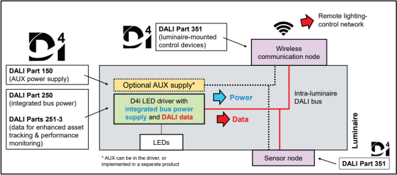
4.2 D4i LED control gear
The LED control gear that meets the D4i certification standard must support DALI data support capabilities, including part 251, 252, and 253.
- DALI Part 251: Light fixture data
- DALI Part 252: Energy data
- DALI Part 253: Debugging data to support the bus supply while optionally supporting the assistance auxiliary DC power supply:
- DALI-250: DALI integrated bus power supply (mandatory)
- DALI-150: AUX auxiliary power supply (optional, LED driver for outdoor or high-power industrial)
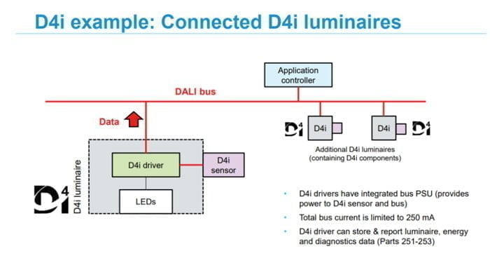
The D4i LED driver has an integrated DALI bus power supply, which can supply power to the DALI control device connected on the bus. In the application of smart lamps, the ability to integrate DALI sensors or other control devices that are only powered by DALI bus. For control devices with high power requirements (such as wireless communication control equipment for road lighting), auxiliary 24V power supply is also required. It can be integrated into the LED control device, or it can be provided by separate power equipment.
4.3 D4i control device
DALI 351 is a standard for D4i control device, and control equipment that can be installed inside the lamp or connected to the lamp. The D4i device requires DALI bus or auxiliary power supply.
DALI Part 351 defines the standards of four different types of control devices (A-D), and also stipulates the specific requirements of the power consumption of the device. It defines how to determine which control device priority when there are multiple control devices. Type A-D includes indoor and outdoor applications, including wireless network lighting controllers, light sensors, motion sensors and timers.
4.4 Zhaga D4i control device and lamps
For the interconnection that is used to plug and play, D4i technology can also be used with various standard socket connectors, such as Nema/ANSI C136.41 and Zhaga Book 18 and Book 20 connectors. The DALI Alliance and Zhaga cooperate closely to formulate a joint Zhaga-D4i certification plan for using the Zhaga socket and D4i LED-driven power supply, and the controller that uses Zhaga plugs and D4i standards. Zhaga-D4i lamps are the use of D4i power and lamps with Zhaga sockets. The road lamps use Zhaga Book18 sockets and indoor lamps Zhaga Book 20 connectors.
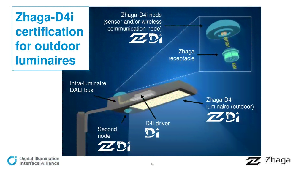
The confirmed Zhaga-D4i product can have dual logos of Zhaga and D4i, indicating that the sensor, control device and lamps have the interpretability of plug-in and play. The intelligent lighting ecosystem composed of Zhaga-D4i lighting products (lamps, control devices, control devices, sensors), which enables smart LED lamps to have the future expansion capabilities of the Internet of Things connection, which greatly enhances the competitiveness of smart lamps and control devices.
5. DALI Wireless Solution
5.1 DALI wireless solution overview
In some cases, wireless lighting control is regarded as an ideal solution, especially in modified projects. The advantage of wirelessness is flexibility. When adding new devices to the existing lighting network or renovating or re-adjusting the use of uses in the building, there is no need to lay communication cables on the wall, ceiling or floor. It can be in terms of time and expenses. This has great advantage in terms of time and expenses.
However, the wireless network also has problems such as network connection stability and coverage. For smart lighting applications of large buildings, it is more suitable to use cable network connections. The cable network system provides predictable network behaviors and avoid any potential connection problems that may occur in the building environment. (The communication cable of the cable DALI network can be installed with the power cord, which has good convenience).
In order to provide wireless connections for supplement, the DALI Alliance provides two wireless solutions.
Scheme 1: Wireless to DALI gateway
Wireless to DALI gateway allows non-DALI wireless ecosystems to use existing DALI wired products to provide transformations of wireless protocols and DALI protocols. The wireless side of the gateway is a wireless node of the wireless ecosystem. The DALI side of the gateway can connect a single D4i or DALI-2 lamp, or a wired DALI-2 network with multiple devices. The gateway is connected to two systems (wireless networks and DALI wired networks or D4i lamps) and converts between protocols. The gateway allows the wireless system to control DALI devices and support the query of lamp fault information.
In addition, the DALI control device can also report lamps asset information, energy information and diagnostic information to the wireless system through the gateway.
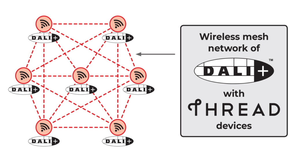
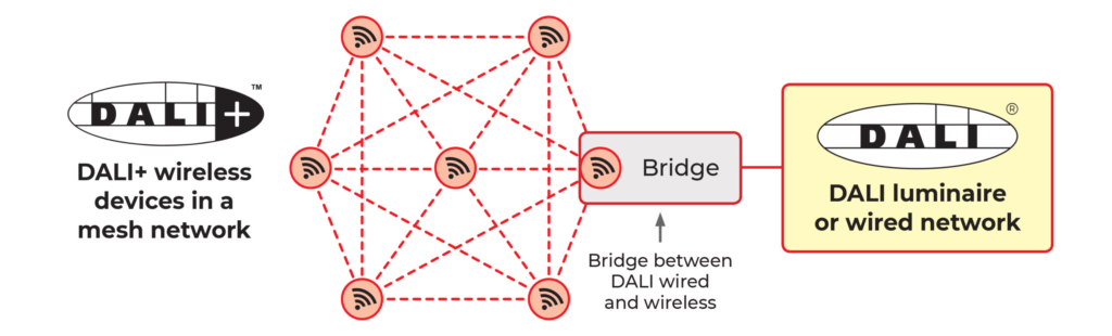
Scheme 2: Wireless DALI Network: DALI+
This method is to communicate with the existing DALI command with the control device and transmit it through the wireless way. DALI wireless device forms a wireless network on its own without having to change between protocols. Wireless DALI can use the same lighting control function in DALI-2 and D4i.
The DALI Alliance has written new standard specifications for wireless DALI+, which has changed and supplemented the 104th part of the existing IEC 62386 standard. Part 104 describes how DALI is transmitted through different vectors, including commonly used DALI bus transmission, wireless transmission and IP-based transmission carriers.
5.2 DALI+
“DALI+” is a new brand launched by DALI Alliance in May 2021, representing DALI instructions and data that can be transmitted through wireless and IP-based networks.
DALI+ is a new standard based on the two mature DALI lighting control standards, which is a cable DALI (DALI-2) and D4i. It can provide more communication and transmission links for control devices, lamps and sensors. DALI+ devices use existing DALI instructions to communicate, but these instructions are transmitted through wireless networks and/or IP-based networks, rather than DALI bus used for transmission.
Based on this, the DALI Alliance released a new DALI standard, “DALI Part 104 Changes & Additions-DALI”. This standard defines how DALI+ can communicate through different network transmission mediums, while introducing authentication of DALI+ device at the same time, thereby realizing the exchangeability and compatibility of DALI+ devices. The first to introduce DALI+ certification is to use Thread-based DALI+, which is a low-power, IP-based wireless grid network communication protocol.
The release of DALI+ has created a new era of standardized lighting industry. Through seamless support for different media such as wired, wireless, and IP networks, it provides lighting designers and users with more choices, flexibility and freedom of creative creation.
- DALI+ is the DALI on the network of wireless and IP (Internet Protocol)
- DALI+ device uses existing DALI instructions to communicate, transmitted through wireless and/or based on IP networks, no DALI-2 and D4i bus
- Compatible with DALI-2, which can allow DALI-2 devices to access the DALI+ network
- Compatible with D4i, compatible with control device, lamp and sensor information acquisition and access function (part 251-253)
6 DALI Alliance and External Organization Cooperation
6.1 DALI Alliance and IEC
The International Electrotechnical Commission (IEC) published IEC 62386-International DALI Technical Documents. At present, most of the latest DALI standards have been included in this international standard, and other parts that are not yet completed are also underway.
6.2 DALI Alliance and ANSI
The American National Standards Institute (ANSI) released a new standard ANSI C137.4-2019, titled ” Lighting Systems-Digital Interface with Auxiliary Power”. The DALI Alliance is a representative of the ANSI Acknowledge Standard Committee (ASC) Lighting System C137, which formulates this standard. ANSI C137.4 is based on DALI standard IEC 62386, which has the additional features consistent with the D4i series.
6.3 DALI Alliance and Zhaga Alliance
Zhaga is a global lighting-industry organization that aims to standardize interfaces of components of LED luminaires, including LED light engines, LED modules, LED arrays, holders, electronic control gear (LED drivers), connectors and sensing/communication modules. The word Zhaga is not an acronym, so it doesn’t mean anything. Zhaga is the name of a waterfall in Sichuan Province of China. Zhaga Consortium was established in 2010. Since then, hundreds of companies have joined this community. Zhaga is publishing a series of books.
- Zhaga uses the term “LED light engine” to describe the combination of LED modules and its associated electronic control devices.
- As long as the supplier uses a compatible interface, it can provide a unique LED light engine.
On March 14, 2018, the Zhaga Alliance and the DALI Alliance reached a cooperative relationship on the IoT solution in the lighting field.
Zhaga released a Book 18 for outdoor LED lighting to increase the characteristics of the Internet of Things. The DALI-based interface protocol is selected as an interface standard for outdoor LED lighting lamps to external sensors (or lighting control devices).
In addition, the Zhaga Alliance and the DALI Alliance also launched a joint certification of Zhaga-D4i. D4i is the trademark of the DALI Alliance. If the product meets the requirements of Zhaga Book 18 (or Book 20), the product can also put the trademark of Zhaga.
7 FAQ
We have summarised all the FAQs in one page, click to see how it can help you.