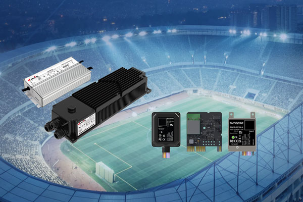
In the era of carbon neutrality and smart infrastructure, lighting systems have evolved from simple illumination into dynamic nodes for energy and data management. However, ensuring deep compatibility between high-power LED drivers and advanced wireless control platforms remains a core challenge for luminaire OEMs and system integrators.
To bridge this gap and accelerate the development of next-generation smart lighting, uPowerTek and Synapse Wireless have co-authored this comprehensive Technical White Paper: uPowerTek LED Drivers & Synapse DIM10-087-06 System Compatibility & Integration Guide.
Authored by uPowerTek founder George Mao and DALI Alliance board member Michael Davidson, this guide provides a standardized, scalable framework for industrial, sports, and architectural lighting. From 12-24V AUX power matching to advanced D4i-powered predictive maintenance and 70ms “Fast Dimming” precision for RGBW applications, this document establishes a proven roadmap for high-performance networked lighting control.
1. Introduction
1.1 Document Purpose
As the official Technical Compatibility Guide for uPowerTek LED Drivers and Synapse DIM10-087-06 embedded intelligent lighting control systems, this white paper provides a comprehensive technical framework that ensures seamless integration between the two product platforms. The document systematically clarifies hardware connection specifications, communication protocol alignment, functional implementation workflows, and engineering commissioning best practices to support reliable deployment in a variety of applications.
Aligned with mainstream North American lighting control standards while drawing upon proven domestic engineering practices, this guide delivers complete support for system integrators—from design and specification, through installation and commissioning, to operation and maintenance. The objective is to ensure continuous system stability, precise dimming and color-control performance, and optimized energy efficiency in industrial, sports, commercial, and architectural lighting scenarios.
This paper highlights the high DALI-2/D4i compatibility and RGBW full-color control excellence of uPowerTek LED drivers, including high color fidelity, smooth dimming, and rapid dynamic scene response. When paired with Synapse’s networked intelligent control capabilities, these drivers provide a standardized, scalable solution that helps luminaire manufacturers significantly shorten development cycles for next-generation smart lighting products.
1.2 Scope of Application
Product Scope
This document covers the integration and application of:
• uPowerTek Outdoor LED Drivers — including 0–10V dimming models, D4i-certified drivers, and multi-channel (RGBW) variants.
• Synapse Wireless DIM10-087-06 Embedded Intelligent Controllers, version V2.1 or later, operating with firmware V3.5+ to ensure full support of D4i functionality, including data reporting and advanced control features.
Scenario Scope
The solutions and recommendations within this guide apply to a wide range of indoor and outdoor lighting environments, including:
• Industrial lighting — high-bay production facilities, cold-chain logistics centers, and automated sorting warehouses
• Sports and recreation lighting — school training fields, community stadiums, and performance venues
• Municipal and infrastructure lighting — underground parking areas, pedestrian walkways, and transportation corridors
• Advanced RGBW control environments — such as commercial retail displays, brand-focused architectural lighting, and dynamic arena lighting for entertainment and atmosphere creation
These scenarios benefit from high-precision dimming, robust data analytics, predictive maintenance capabilities, and seamless integration with networked lighting control platforms.
1.3 Core Value and Industry Significance
Under the global push toward carbon neutrality and rapid development of intelligent buildings, lighting systems are shifting from basic illumination to becoming dynamic nodes for energy and color management. The joint solution from uPowerTek and Synapse Wireless leverages the strengths of high-reliability LED drivers and precise networked lighting controls to unlock three core values:
• Dual-Protocol Compatibility
Supporting both 0–10V analog and DALI-2 digital dimming, this architecture seamlessly adapts to retrofit and new-build applications. Customers can modernize systems without costly infrastructure changes—protecting existing investments while enabling future upgrades.
• D4i Intelligent Management
Through real-time performance data, such as luminaire temperature, voltage, and output current, the system enables automated alerts and predictive maintenance workflows. This reduces manual inspection, cutting operation and maintenance effort by over 60% while ensuring continuous, high-efficiency lighting performance.
• RGBW Full-Color Precision Control
With high-quality color reproduction and rapid response, the solution supports immersive lighting scenes for commercial displays, stadiums, and entertainment environments. Dynamic control capabilities enable both visual impact and true operational flexibility.
By standardizing advanced controls and data at the fixture level, this integrated solution accelerates the evolution of intelligent lighting—from “high-end customization” to large-scale, repeatable deployment. It establishes a proven energy-optimization framework that is scalable across industries and aligned with the global “dual-carbon” sustainability objectives.
2. Core Product Technical Parameters and Compatibility Foundation
2.1 Detailed Explanation of Core Product Parameters
The technical compatibility of the two products must be based on parameter matching. The following is an in-depth analysis of key parameters and explanation of matching logic:
2.1.1 Core Parameters of Synapse DIM10-087-06 Series Controller
| Parameter / Feature | Input Voltage/Power | Enclosure / Description | Ingress Protection | Output Signal |
| DIM10-087-06 | 12–24 VDC/900mW | Bare board, external antenna enabled, (RF cable and antenna not included) | None | 0–10 V analog dimming (10 mA source/sink) and DALI 2 (D4i) bus (up to 4 LED drivers) |
| DIM10-087-06-F | 12–24 VDC/900mW | Bare board, internal PCB antenna enabled | None | 0–10 V analog dimming (10 mA) and DALI 2 (D4i) bus (up to 4 drivers) |
| DIM10-087-06-A(Most Applied) | 12–24 VDC/900mW | Board in metal enclosure with 7 wires; includes antenna extension cable (external antenna not included) | IP30 | 0–10 V analog dimming (10 mA) and DALI 2 (D4i) bus (up to 4 drivers) |
| DIM10-087-06-FW | 12–24 VDC/900mW | Bare board, internal antenna enabled with 7 wires | None | 0–10 V analog dimming (10 mA) and DALI 2 (D4i) bus (up to 4 drivers) |
| DIM10-087-06-F3W | 12–24 VDC/900mW | Bare board, internal antenna enabled with 3 wires (dimming only) | None | 0–10 V analog dimming (10 mA) only (no DALI output) |
| DIM10-087-06-IP | 12–24 VDC/900mW | Board in waterproof enclosure with 6 wires; internal antenna enabled | IP66 | 0–10 V analog dimming (10 mA) and DALI 2 (D4i) bus (up to 4 drivers) |
2.1.2 Core Parameters of uPowerTek Single Channel LED Drivers
| Driver Model | Input Voltage | Output Power | Control Interface Characteristics | Auxiliary Power |
| BLD Series Single Channel IP67 Isolated Driver | 120-277V | 40 ~ 1000W | 0-10V Dimming (100uA Sourcing Current)DALI-2 Dimming (60mA Current) | 12V DC/300mA |
| BLD Series D4i Single Channel IP67 Isolated Driver | 120-277V | 40 ~ 500W | D4i Dimming (60mA Current) | 24V DC/150mA |
| TLD Series Single Channel IP67 Isolated Driver | 200-480V | 160 ~ 1200W | 0-10V Dimming (100uA Sourcing Current)DALI-2 Dimming (60mA Current) | 12V DC/300mA |
| TLD Series D4i Single Channel IP67 Isolated Driver | 200-480V | 600 ~ 1200W | D4i Dimming (60mA Current) | 24V DC/150mA |
| BLK Series Single Channel IP67 Non-isolated Driver | 120-277V | 400 ~ 800W | 0-10V Dimming (100uA Sourcing Current)DALI-2 Dimming (60mA Current) | 12V DC/300mA |
| CLK Series D4i Single Channel IP67 Non-isolated Driver | 120-347V | 400 ~ 800W | 0-10V Dimming (100uA Sourcing Current)D4i/DALI-2 Dimming (60mA Current) | 12V DC/300mA |
| SLK Series D4i Single Channel IP67 Non-isolated Driver | 200-480V | 600 ~ 1200W | 0-10V Dimming (100uA Sourcing Current)D4i/DALI-2 Dimming (60mA Current) | 12V DC/300mA |
| TLK Series D4i Single Channel IP67 Non-isolated Driver (NEW) | 200-480V | 1000 ~ 1600W | D4i Dimming (60mA Current) | 12V DC/300mA |
2.1.3 Core Parameters of uPowerTek Multi-Channel LED Drivers
| Driver Model | Input Voltage | Output Power | Control Interface Characteristics | Auxiliary Power |
| BLD Series Multi-channel IP67 Isolated Driver | 120-277V | 200 ~ 800W | DALI-2 Dimming (60mA Current) | 24V DC/150mA |
| BLD Series D4i Multi-channel IP67 Isolated Driver (NEW) | 120-277V | 300 ~ 500W | D4i Dimming (60mA Current) | 24V DC/150mA |
| TLD Series Multi-channel IP67 Isolated Driver | 200-480V | 300 ~ 800W | DALI-2 Dimming (60mA Current) | 24V DC/150mA |
| TYK Series D4i Multi-channel IP67 Non-isolated Driver | 200-480V | 600 ~ 2000W | D4i Dimming (60mA Current) | 24V DC/150mA |
| TLK Series D4i Multi-channel IP67 Non-isolated Driver (NEW) | 200-480V | 1000 ~ 1600W | D4i Dimming (60mA Current) | 24V DC/150mA |
2.2 Core Criteria for Compatibility Evaluation
The compatibility of the two products must meet the four principles of “power supply compatibility, signal matching, protocol interoperability, and environmental consistency”:
- Power Supply Compatibility: When powering a Synapse DIM10-087 series controller from an LED driver, the driver must provide a stable 12–24 VDC auxiliary output. The controller requires approximately up to 0.9W, so the driver’s AUX output must supply adequate current with margin, especially if additional sensors share the same supply. A Class 2–rated AUX (or D4i-compliant AUX for D4i drivers) is recommended for safety and compatibility.
- Signal Matching: The source/sink capability of the 0-10V dimming signal matches the driver’s input impedance (the controller’s 10mA capability can cover the driver’s 150uA sourcing current, theoretically 60pcs of drivers).
- Protocol Interoperability: For system status report and DALI communication, the controller firmware must support D4i extended commands (such as “read luminaire temperature” and “fault reporting”), and the driver must have DALI2/D4i certification .
Dynamic Response Consistency and Fast Dimming:
Fast dimming enabled by uPowerTek LED drivers combined with Synapse’s SimplySNAP control platform delivers the high-speed, low-latency lighting performance required for sports applications, dynamic color effects, and rapid scene transitions. Compared with conventional 0–10 V dimming approaches, uPowerTek Fast Dimming drivers provide significantly accelerated response times with precise and repeatable behavior.
When configured in FAST mode, the driver supports:
- 10–90% output transitions within ~70 ms
- Near-instant On/Off transitions:
- ~300 ms for isolated BLD/TLD single-channel drivers
- ~30 ms for non-isolated BLK/CLK/SLK/TYK/TLK single channel drivers and isolated BLD/TLD multi-channel drivers
These rapid response rates ensure smooth modulation, flicker-free operation, and consistent behavior even during high-speed sequencing.
The Synapse networked lighting controller complements this capability by issuing high-frequency dimming commands that synchronize through SimplySNAP’s dynamic effects engine. This coordinated control enables professional-grade lighting behaviors such as flashing, strobing, smooth fades, chase patterns, and other visually impactful transitions—ideal for both entertainment and performance-driven lighting scenarios.
- Environmental Consistency:To ensure long-term reliability and minimize environmental-related failures, the operating temperature, humidity tolerance, and ingress protection level (IP rating) alignment between the LED drivers and the connected Synapse controllers must reach an overlap rate of ≥ 95%. This high degree of environmental consistency reduces risks of malfunction due to any single device exceeding its specified environmental limits and helps maintain stable performance across demanding industrial and outdoor deployments.
For example, in cold-storage warehouses or outdoor sports lighting installations, the luminaire’s driver and controller may experience extreme temperature swings and high moisture levels. Ensuring tightly matched environmental ratings prevents interruptions in communication or lighting operation, even during harsh weather or sustained low-temperature conditions.
2.2 Compatibility Consideration
Here is the major aspects of compatibility consideration.
| Parameter Category | DIM10-087 Specific Specifications | Compatibility Requirements | Engineering Significance |
| Power Supply Requirement | 12-24V DC, power consumption ≤ 0.9W | The auxiliary power output of uPowerTek driver shall be within 5-24V, with current ≥ 300mA | Wide-voltage adaptation reduces power supply selection difficulty, and low power consumption complies with green building standards |
| Control Output | 0-10V dimming: 10mA source/sink capability, linearity ±1%DALI-2: Complies with IEC 62386-101/102/207, supports D4i extended commands | 0-10V shall match the driver dimming interface type; DALI 2.0 or D4i | High-precision dimming ensures smooth, accurate light control for specialized applications such as sports venues and architectural displays. With DALI-enabled intelligent diagnostics, the system can proactively identify performance issues, improve maintenance efficiency, and maintain long-term operational stability. |
| Fast Dimming | Fast Dimming Transition: ~70 ms from 10% to 90% outputQuick On/Off Transition: ~300 ms from 0% to 100% output | FAST-capable LED drivers, such as uPowerTek BLD, TLD, SLK, BLK, TYK series | Fast Dimming empowers the Synapse lighting system to deliver rapid, smooth, and precisely controlled dynamic effects—such as flashing, pulsing, strobing, and seamless color transitions. This high-speed responsiveness is essential for sports lighting, entertainment venues, and any environment where lighting must synchronize perfectly with motion, music, or event-driven cues. |
| Wireless Communication | SNAP mesh network, 2.4GHz frequency band, communication distance 300ft (open area)/50ft (industrial obstruction) | Synapse CBS (central base station) gateway is required to ensure no blind spots in signal coverage | Self-healing, self forming wireless network ensures communication stability in tough RF enviroments such as complex industrial environments and sporting venues, “It just Works!” |
| Environmental Adaptability | Temperature-40℃~80℃, humidity 10%~90% (non-condensing) | The environmental parameter overlap rate with uPowerTek driver is ≥ 95% | Adapts to extreme environments such as cold chain and high-temperature workshops, reducing failure risks |
3. Core System Compatibility Solutions
3.1 Power Supply Compatibility Solution
3.1.1 Power Supply Link Design and Engineering Wiring
The DIM10-087-06 adopts a direct auxiliary power approach by drawing power from the LED driver’s auxiliary supply. This removes the need for an independent power module within the luminaire, simplifying system design, reducing material cost, and eliminating redundant components that could affect long-term reliability.
Energy Conversion Link: After the uPowerTek driver is connected to 120-277V AC mains, it realizes dual output through the internal AC/DC conversion circuit—the main circuit outputs constant current to drive the LED load, and the auxiliary power circuit outputs stable 12V/24V DC voltage, specifically for powering the controller and peripherals .
Wiring Specifications: Use 18–22 AWG, stranded, UL-rated, 600 V control cable for AUX power and dimming lines. Shielded cable is recommended for long runs or noisy environments to reduce interference. Keep control wiring separate from driver AC mains to prevent noise coupling and safety. In multi-driver setups, parallel all DIM+/DALI connections and stay within the DIM10-087-06 supported driver count.
Startup Logic: After the driver is powered on, the auxiliary power supply establishes the voltage within 20ms, and the controller initializes synchronously (the indicator light flashes green three times), then connects to the SimplySNAP wireless network (solid green light indicates successful network connection), realizing the synchronous response of “driver startup – controller readiness” .
3.1.2 Key Notes for Power Supply Matching
Voltage Matching and Adaptive Mechanism:
The controller integrates a wide-voltage regulation chip that automatically adapts to different auxiliary power sources, ensuring reliable operation across multiple luminaire designs. It supports:
• 12 V auxiliary power commonly used in uPowerTek single-channel drivers
• 24 V auxiliary power available in D4i-certified drivers and multi-channel DALI-2 solutions
This adaptive supply design eliminates compatibility concerns, simplifies luminaire integration, and enhances system robustness in diverse field deployments.
Current Redundancy Design: The controller’s rated operating current is 100mA and the maximum power is 900mW. uPowerTek 12V/300mA or 24V/150mA provides sufficient capacity to power a single DIM10-087-06. . However, users must account for short-duration periods when the DIM10-087-06 operating current may temporarily exceed 100 mA (e.g., during startup). If an auxiliary power supply from another brand cannot support these transient current peaks, the controller may fail to start up reliably.
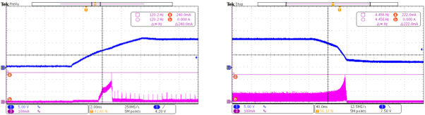
Blue CH1:BLD series 12Vaux voltage DC Purple CH3: DIM10-087-06 operation current
If an external PIR sensor (such as a WattStopper FSP-201 or equivalent) is required, the driver’s auxiliary power 300mA output can meet the simultaneous power supply of “controller + sensor” without additional capacity expansion.
Ripple Control Requirement: The driver’s auxiliary power shall be as small as possible, suggested to be ≤ 300mV (e.g., uPowerTek driver working with DIM10-087-06 has typical ripple value of less than 150mV). If the ripple is too large (exceeding 500mV), it may cause the controller’s wireless communication to be unstable. Here is a typical waveform of 12Vaux power and operation current.
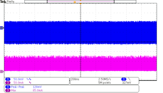
Blue CH1:BLD series 12Vaux voltage DC Purple CH3: DIM10-087-06 operation current
3.2 0-10V Dimming Compatibility
3.2.1 Hardware Connection Specifications and Pin Definition
As the most widely used analog dimming method in the current market, the connection reliability of 0-10V dimming directly affects the dimming effect. The 0-10V interfaces of DIM10-087-06 and uPowerTek driver adopt the “point-to-point direct connection” mode, without additional adapter modules. The specific wiring definitions and engineering requirements are as below:
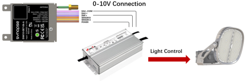
| Function Definition | uPowerTek Driver Interface | uPowerTek Driver Wiring Color Standard | DIM10-087-06 Interface | DIM10-087-06 Wiring Color Standard |
| 0-10V dimming signal positive | Vdim+ | Purple | DIM+ | Violet |
| 0-10V dimming signal negative and auxiliary power supply negative | Vdim- | Pink | COM | Pink/white |
| Auxiliary power supply positive | Vaux | Black/white | Power | Brown |
Key Engineering Tips:
- Before wiring, use a multimeter’s continuity range to test the wire to avoid dimming unresponsiveness caused by broken wires.
- The driver’s Vdim- and controller’s COM must be connected in common to form a unified signal reference ground.
3.2.2 Dimming Function Implementation Logic and Performance Indicators
The Synapse DIM10-087 series controller enables highly reliable wireless dimming control for uPowerTek LED drivers, supporting both standard 0–10 V dimming with Dim-to-Off and DALI-2/D4i digital control. Operating as a key node in the SimplySNAP 2.4 GHz mesh network, the controller receives wireless lighting commands and converts them into stable, precise dimming signals that align with uPowerTek driver specifications.
Designed for seamless luminaire integration, the DIM10-087 series supports 12–24 VDC auxiliary power and provides either controlled 0–10 V outputs (maximum 10 mA source/sink) or IEC 62386-compliant DALI-2 communication. This protocol flexibility allows a single controller to address diverse project environments—from retrofit systems relying on analog dimming to advanced D4i architectures requiring full digital feedback and diagnostics.
When operating in 0–10 V mode, the controller generates smooth, noise-free analog transitions. The installation guide specifies proper COM wiring, separation from AC lines, and tying all driver DIM-/COM lines together for multi-driver setups. For D4i, the DIM10-087 serves as the single master controller and supports up to four D4i drivers with active bus power. These functions align well with uPowerTek’s linear dimming behavior and high-precision current regulation.
Synapse’s internal dimming-smoothing algorithms ensure gradual, flicker-free light transitions across the full output range. When paired with uPowerTek’s high-speed current-loop response, the combined system delivers consistent dimming behavior in real-time control scenarios—including deep-dimming operation, rapid on/off transitions, and dynamic scene changes. For applications requiring fast, expressive lighting effects, uPowerTek drivers respond at high speed without the need for special firmware or field configuration, offering a clear performance advantage over standard driver implementations.
Performance indicators for the combined solution include precise low-level dimming, high-speed visual response, and excellent channel-to-channel consistency—critical for RGBW and dynamic lighting effects. DALI-2 features such as linear dimming, On/Off control, and optional power-metering enable system-level visibility and diagnostics through the lighting network.
Network-synchronized commands delivered by the SimplySNAP platform ensure brightness uniformity across large installations, while reliable AUX-power support and correct wiring practices maintain long-term operational stability and reduce commissioning risks.
Overall, the DIM10-087 and uPowerTek LED drivers deliver a highly compatible, high-performance dimming platform well suited for outdoor, architectural, and sports lighting applications that demand smooth, reliable, and fast-responding control.
3.2.3 Engineering Debugging Steps
Power & AUX Verification: Begin by confirming the LED driver’s 12–24 VDC AUX output is correctly wired to the controller’s power input as defined. Make sure the Driver is not powered when connecting the DC power to the controller. Measure the voltage to ensure it is within ±10% tolerance. Confirm proper grounding to avoid ESD-related controller damage. The Common wire should not be tied to earth ground.
Wiring Continuity & Polarity Checks: Verify that DIM+/DIM– or DALI+/DALI– are properly connected. For multi-driver 0–10 V systems, ensure all DIM-/COM wires are tied together as instructed. Check for shorts, reversed polarity, or improper grounding. The common wire should not be tied to earth ground. If the common is tied to earth ground, erratic results are possible. Ensure dimming wires are routed away from AC conductors to reduce interference.
0–10 V Signal Validation: With the fixture powered, measure the 0–10 V DIM+ line and confirm voltage changes when sending commands from SimplySNAP. Voltage should smoothly vary from 0–10 V without jumps. Verify correct dimming voltage by checking 4-5 dimming levels. If dimming is non-responsive, test with the driver disconnected to isolate controller output.
DALI/D4i Bus Diagnostics: For D4i systems, confirm no more than four drivers with active bus power are connected. Confirm driver addressing through the SimplySNAP controller. Check the 250 mA bus current limit and verify that unused wires are capped.
D4i Aux Power Supplies: Makes sure only one D4i power supply is connected to the DIM109-087-06. Cap additional D4i Aux Power Supplies.
Controller Communication & Status LEDs: Observe the DIM10-087 status LED behavior: red indicates no network, green indicates normal operation. Confirm antenna placement. Remove nearby metal objects and verify the antenna is not resting at or near ground level. RF performance can be affected by these conditions.
Functional Testing with uPowerTek Drivers: Send dimming commands through SimplySNAP and verify smooth transitions across the full dimming range. If flicker or delayed response appears, confirm driver configuration, wiring integrity, and AUX stability.
3.3 DALI Output Compatibility
3.3.1 Protocol Compatibility Foundation and Core Value
As an international standard for digital dimming, DALI-2 (IEC 62386) offers clear advantages over traditional 0–10 V analog dimming, including precise control, bidirectional communication, and flexible grouping. As an extension of DALI-2, D4i further enables intelligent luminaire management by standardizing power, data, and diagnostics at the driver level.
Both DIM10-087-06 and uPowerTek D4i-series drivers are D4i certified and support the full D4i command , including functions defined in IEC 62386-207 such as luminaire temperature monitoring and fault-type reporting. Working together, they go beyond basic dimming to form a closed-loop intelligent lighting system that integrates perception, control, and diagnostics, enabling more reliable operation, enhanced visibility into luminaire performance, and simplified long-term maintenance.
3.3.2 Bus Topology and Connection Specifications
The DALI bus uses a two-wire, polarity-free differential communication method. Proper topology design is critical to ensure reliable communication, accurate diagnostics, and long-term system stability. The DALI bus must follow a linear (daisy-chain) topology to minimize reflections and signal attenuation that can occur with improper wiring.
Topology Structure
- DIM10-087-06 functions as the DALI master (controller) on the bus.
- The uPowerTek D4i-certified LED driver functions as a DALI slave device.
- Multiple D4i drivers may be connected on the same DALI bus, subject to 250mA Bus current limit.
Hardware Connection: The DALI interfaces of DIM10-087-06 and uPowerTek driver adopt the “point-to-point direct connection” mode, without additional adapter modules. The specific wiring definitions and engineering requirements are as follows:
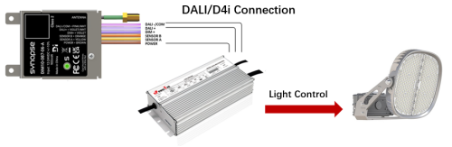
| Function Definition | uPowerTek Driver Interface | uPowerTek Driver Wiring Color Standard | Synapse DIM10-087-06 Interface | Synapse DIM10-087-06 Wiring Color Standard |
| DALI dimming signal positive | DA+ | Purple | DALI+ | Violet |
| DALI dimming signal negative and auxiliary power supply negative | DA- | Pink | DALI- | Pink/white |
| Auxiliary power supply positive | Vaux | Black/white | Power | Brown |
Bus Power Supply: The DALI bus power supply is provided by the uPowerTek driver with a built-in 16V DALI-2 power supply as specified in uPowerTek product datasheets. This integrated supply powers the DALI control bus directly and eliminates the need for an external DALI power module.

The Synapse controller, acting as the DALI master device, does not need to source bus power. This architecture reduces system complexity and improves overall reliability by centralizing bus power within the luminaire driver.
Many DALI-2 LED drivers on the market do not include a full 16 V / 60 mA DALI bus power supply and therefore cannot independently power a DALI network. When used with Synapse lighting controllers, the system must include at least one DALI-2/ D4i-compliant LED driver capable of supplying the required DALI bus power. D4i-certified drivers inherently meet this requirement and are fully suitable for powering the intra-luminaire DALI bus.
Quick Question:
1.How many drivers can be connected with a single Synapse DIM10-087-06?
Answer from Synapse datasheets:

According to the DALI standard (IEC 62386), a DALI bus is limited to a maximum supply current of 250 mA. As mentioned, uPowerTek LED drivers include an internal DALI power supply and are typically specified to contribute approximately 60 mA each to the DALI bus.
Therefore:
4 drivers → 4 × 60 mA = 240 mA (within the DALI limit)
5 drivers → 5 × 60 mA = 300 mA (exceeds the 250 mA limit)
2.What if 5 or 6 drivers are needed with single controller?
uPowerTek DALI multiple channel drivers can be used to reduce the quantity to 2 drivers.
3.3.3 Core Intelligent Function Implementation (D4i Features)
Compared with 0-10V or DALI-2 systems, the cooperation of D4i protocol realizes three intelligent functions as below.
| Function Category | Implementation Logic (Command Interaction) | Engineering Application Value |
| Automatic Device Identification | The controller sends the “read device ID” command (DALI command 0x23), and the driver returns data including model, firmware version, and serial number, which is automatically entered into the SimplySNAP platform | Replaces manual entry, reduces 90% of device information statistics time, and avoids entry errors |
| Real-time Status Monitoring | The controller captures D4i LED Driver Input Current, Input Voltage, and Power data. | Realizes the visualization of luminaire operating status and provides data support for energy management |
| Fault Prediction and Reporting | “SimplySNAP detects and reports anomalies with the LED Driver and LED Array daily. This information allows meaningful intelligence on issues with the luminaire. Current Foldback, Over Voltage, Under Voltage, Over Temperature, LED Array Short Circuit, and LED Array Open Circuit. | Converts from “passive maintenance” to “active early warning”, reducing unplanned downtime |
3.4 RGBW Control Application with DALI Output
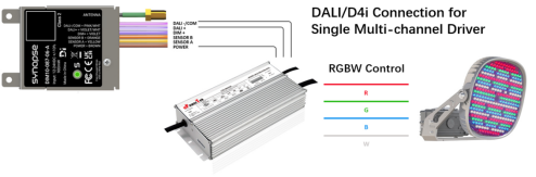
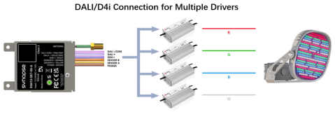
3.4.1 How Synapse + uPowerTek Driver Achieve RGBW Control
To realize RGBW (or RGBAW) control, Synapse SimplySNAP directly controls four channels by either traditional 4 drivers or a single 4-channel driver, each responsible for one color channel individually over DALI-2/D4i. This is the key concept. One color = one driver or one channel of a single driver. So an RGBW fixture uses 4 drivers or one 4-channel driver.
RGBAW uses 5, and max allowed by Synapse = 6 drivers.
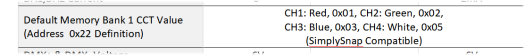
Each uPowerTek driver must be programmed with a “color identity”. Synapse relies on the CCT field in Memory Bank 1 (addresses 0x21 & 0x22) of the D4i memory standard (section 3.4.2).
There are two common architectures for implementing RGBW or multi-color lighting control using uPowerTek LED drivers with the Synapse SimplySNAP control platform: (1) a single driver with multiple outputs, and (2) multiple single-channel drivers.
In the first method, a single uPowerTek multi-channel driver provides multiple constant-current outputs—typically three or four—to power the red, green, blue and white LED arrays. Each channel is controlled independently inside the driver. This approach reduces wiring complexity and minimizes physical components, as well as debugging and maintenance cost.
Here is list of uPowerTek multi-channel drivers:
| Driver Model | Input Voltage | Output Power/Current | Control Interface Characteristics | Auxiliary Power |
| BLD Series Multi-channel IP67 Isolated Driver | 120-277V | 200 ~ 800W | DALI-2 Dimming (60mA Current) | 24V DC/150mA |
| BLD Series D4i Multi-channel IP67 Isolated Driver (NEW) | 120-277V | 300 ~ 500W | D4i Dimming (60mA Current) | 24V DC/150mA |
| TLD Series Multi-channel IP67 Isolated Driver | 200-480V | 300 ~ 800W | DALI-2 Dimming (60mA Current) | 24V DC/150mA |
| TYK Series D4i Multi-channel IP67 Non-isolated Driver | 200-480V | 600 ~ 2000W | D4i Dimming (60mA Current) | 24V DC/150mA |
| TLK Series D4i Multi-channel IP67 Non-isolated Driver (NEW) | 200-480V | 1000 ~ 1600W | D4i Dimming (60mA Current) | 24V DC/150mA |
The second method uses multiple uPowerTek single-output drivers, with one driver per color channel. Each driver powers one LED array and appears on the DALI bus as an independent device. The installer programs each driver with a unique color identifier using MB1 (Memory Bank 1), enabling Synapse to automatically recognize which driver controls Red, Green, Blue, White, or Amber. This method is fully compatible with SimplySNAP and allows Synapse to perform color mixing, scenes, and dynamic effects by sending individual DALI dimming commands to each driver.
3.4.2 DALI-2/D4i Programming Considerations
DALI/D4i Driver Programming Prerequisites: For RGBWA functionality, use SimplySNAP software ≥V13.4 and activate the Synapse Sports License (LM-SPORTSPRO). Each color channel (R/G/B/A/W) requires a dedicated DALI/D4i driver, with a maximum of 4 drivers per controller (per Synapse RGBWA specifications) .
Color Designator Programming: The drivers not recognized by the controller are often due to missing color designator programming. The CCT register (0x21=0x00, 0x22=color code) must be programmed via NFC or DALI tool. The color codes are: 1=Red, 2=Green, 3=Blue, 4=Amber, 5=White. After programming, immediately label drivers to prevent wiring errors. uPowerTek multi-channel LED drivers set the programming in factory as the content below from datasheets shows.
For single channel driver, uPowerTek also pre-sets the parameters in factory.
4. System Debugging and Troubleshooting
4.1 Full-Process Debugging Specifications
Debugging a lighting system that combines the Synapse DIM10-087 controller and uPowerTek LED drivers requires a structured approach across power integrity, wiring correctness, network communication, and dimming behavior. Because both components are designed for high-performance outdoor, industrial, sports lighting, and architectural lighting, most issues originate from wiring, AUX power stability, or system configuration rather than component failure. The following steps outline an effective troubleshooting workflow for engineering, field commissioning, and long-term maintenance.
4.1.1 Verify Power Integrity
Begin by checking that the 12–24 VDC AUX output from the uPowerTek driver supplies clean, stable power to the Synapse controller. The DIM10-087 requires correct polarity (Brown = AUX+, Pink/White Stripe = COM). Using a digital multimeter, ensure voltage remains within specification even during driver inrush or during wireless transmission bursts. If instability appears, inspect the driver’s AUX loading, sensor connections, and grounding. Make sure common is not tied to earth ground. Poor grounding can cause ESD-related controller malfunction.
4.1.2. Confirm Wiring and Polarity
Most dimming issues are caused by incorrect wiring. For 0–10 V DIM-to-OFF systems, verify the Synapse VIOLET (DIM+) and Gray/Pink (DIM-/COMMON) wires are connected precisely as shown in the installation guide. All drivers must share the same DIM-/COM line; any floating or individually isolated returns will result in erratic dimming. For D4i/DALI-2, confirm DALI+/DALI– polarity is consistent, unused wires are capped, and the total number of drivers with active bus power does not exceed Synapse’s limit (maximum 4). Wiring should be routed away from AC lines to prevent noise interference.
4.1.3. Evaluate Dimming Signal Behavior
Once wiring is validated, check the 0–10 V output waveform or measured dimming voltage while sending commands from SimplySNAP. Check 4 to 5 dimming levels for verification. The signal should transition smoothly with no jumps or oscillations. If the signal is correct but the LED output is not responding, temporarily disconnect the driver to confirm whether the DIM10-087 is behaving correctly. uPowerTek drivers respond rapidly to dimming input, so any lag typically points to wiring or controller configuration.
4.1.4. Confirm Controller Network Status
The DIM10-087’s status LED provides critical diagnostic information.
Red indicates the controller is not connected to the SimplySNAP network.
Blinking Green indicates the controller is found but not configured.
Solid Green confirms normal operation.
If network issues occur, inspect antenna orientation, metal obstructions, and nearby RF sources. The controller must have proper antenna placement per the installation guide.
4.1.5. Validate Driver Response and System Behavior
Send multiple dimming levels, on/off commands, and slow-to-fast transitions. uPowerTek drivers are designed for fast current-loop regulation, so they should track Synapse signals precisely. Flicker, delayed response, or color inconsistency in RGBW fixtures typically indicates wiring errors, low DIM voltage due to loading, or improperly tied commons. For DALI systems, ensure the bus is not overloaded and drivers are correctly addressed in SimplySNAP.
4.2 Common Faults and Solutions
| Fault Phenomenon | Possible Causes (Ranked by Probability) | Solutions (Step-by-Step Implementation) |
| DIM10-087-06 fails to power on (red light not on) | 1. Auxiliary power or common wiring error; 2. Driver auxiliary power failure; 3. Controller pin cold solder joint | 1. Use a multimeter to measure the driver’s AUX+/- voltage to confirm normal output; 2. Verify the wiring (V+ connected to AUX+, V- connected to AUX-); 3. Replace the controller for testing (to rule out pin faults) |
| 0-10V dimming brightness fluctuation | 1. Poor dimming line contact; 2. Common tied to earth Ground 3. Excessive driver ripple; 4. Electromagnetic interference | 1. Re-crimp the terminal block, and measure the contact resistance ≤ 0.1Ω with a multimeter; 2. Connect a 100μF capacitor in parallel with the dimming line; 3. Thread the line through a metal pipe and ground it |
| DALI bus communication failure (device offline) | 1. Bus short circuit or open circuit; 2. Excessive number of devices | 1. Verify connections 2.Test the bus with a multimeter’s continuity range; 3. Reboot Drivers and Controller. |
| D4i drivers not recognized by the controller | 1. D4i driver not programmed with color designator; 2. DALI bus not rescanned; 3. Driver firmware version incompatible | 1. Program the CCT register (0x21=0x00, 0x22=color code) via NFC or DALI tool; 2. Click “RESCAN FOR DALI DRIVERS” in SimplySNAP; 3. Upgrade driver firmware to ≥V2.0 |
| RGBW color mismatch (e.g., Red command activates Green LEDs) | 1. Incorrect color code programming in D4i driver; 2. Driver-channel connection error; 3. SimplySNAP color assignment not refreshed | 1. Verify CCT register value (0x22) matches the color (1=Red, 2=Green, 3=Blue, 4=Amber, 5=White); 2. Recheck wiring (Red driver → Red LED module); 3. Click “REFRESH” in Light Details pane |
| Controller frequently offline | 1. Wireless signal blocked by metal obstacles; 2. Gateway distance exceeding 300ft (open area); 3. Excessive auxiliary power ripple | 1. Reposition the external antenna (keep ≥12in away from metal objects); 2. Add a SNAP repeater to extend coverage; 3. Install a 100μF electrolytic capacitor for auxiliary power filtering |
| Dimming curve nonlinearity (0-10V mode) | 1. Driver dimming mode not set to 0-10V; 2. Dimming line voltage drop; 3. Controller DAC calibration required | 1. Set driver DIP switch to “0-10V” mode; 2. Shorten dimming line length (≤1m) 3. Use AWG 18 multi-strand wire; 4. Verify no AC cross talk. |
5. Key Considerations (Engineering Practice Guidelines)
5.1 Equipment Selection and Compatibility Verification
Firmware Version Compatibility: The DIM10-087-06 requires firmware ≥V3.5 to support full D4i functions (e.g., fault reporting, color grouping). Older versions only support basic DALI dimming and must be upgraded via OTA (download from Synapse Developer Portal). uPowerTek D4i drivers need firmware ≥V2.0 to respond to D4i extended commands .
Color Control Prerequisites: For RGBWA functionality, use SimplySNAP software ≥V13.4 and activate the Synapse Sports License (LM-SPORTSPRO). Each color channel (R/G/B/A/W) requires a dedicated D4i-certified driver, with a maximum of 6 drivers per controller (per Synapse RGBWA specifications) .
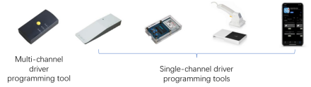
Tool Compatibility: Driver programming requires OEM-specific tools (e.g., uPowerTek NFC programmer, Feig programmer and uPowerTek cable programmer for multi-channel drivers).
5.2 Installation and Wiring Guidelines
Grounding: Proper grounding is required to avoid static discharge, which can damage the controller. Technicians must be grounded with a proper ground strap when handling the antenna cable.
DALI Bus Wiring: Adopt daisy-chain topology only (star/ring topology causes signal attenuation). Do not share the DALI bus wires with mains AC wiring to avoid noise coupling.
Antenna Installation: Choose 50Ω RP-SMA type and check Synapse’s website for kits. Install antenna vertically (up/down), keep ≥2 inches (12 inches for DIM10-087-06-A) from metal, ensure cable bend radius ≥2 inches, make a drip loop against water. Technicians must ground to avoid static; tighten antenna by hand + 1/4 turn (no over-tightening). Route cables away from AC lines/metal enclosures, use ≤6mm-thick fixture walls, and cap unused wires.
Eviromentals (Outdoor Scenarios): When deploying uPowerTek LED drivers together with the Synapse DIM10-087-06 controller in outdoor luminaires, it is essential to ensure that the power and controller box provides at least IP66 protection. Also for the metal case DIM10-087-06-A, it should not be mounted to LED driver case so as to make sure driver does not overheat the controller since the max case temperature of driver is 90℃ and DIM10-087-06-A is 80℃.
5.3 Debugging and Operation & Maintenance Guidelines
Pre-Debugging Safety Checks: Verify input voltage matches the driver’s rating (120-277V AC for North America, 220V AC for China) before power-on. Use an insulation resistance tester to confirm ≥5MΩ between phase and ground wires. Wear insulated gloves and use insulated tools during debugging .
DALI Programming Precautions: Avoid writing short addresses, scene data, or fade parameters to DALI drivers—this disrupts SimplySNAP compatibility. Program only the CCT register (0x21=0x00, 0x22=color code) and luminaire identification. Label drivers immediately after programming to prevent wiring errors .
Configuration Backup: After successful debugging, back up device configurations (zones, scenes, dimming curves) to both local storage and the SimplySNAP Cloud. This enables quick restoration when replacing controllers/drivers .
Routine Maintenance: Inspect terminal tightness quarterly (critical for vibrating industrial environments), clean dust from cooling vents annually, and recheck dimming performance/color parameters every two years. For D4i systems, run a monthly “health check” via SimplySNAP to monitor driver temperature and current .
6. Appendix
6.1 Glossary
| Term | English Full Name | Definition |
| D4i | DALI for IoT | Intelligent lighting protocol based on DALI-2, enabling device identification, Power monitoring, status monitoring, and fault reporting |
| DALI-2 | Digital Addressable Lighting Interface | International standard (IEC 62386) for digital dimming and control |
| SNAP | Simple Network Address Protocol | Synapse’s proprietary wireless mesh network protocol, supporting large-scale node communication |
| CBS | Central Base Station | Core network device for the SimplySNAP wireless control system. It provides the single point of connection between the wireless mesh network of lighting controllers and the internet or local network. It acts as the primary gateway for control and monitoring, relaying commands and data for the entire lighting system. Is capable of being tied to SimplySNAP Cloud. |
| RGBWA | Red/Green/Blue/Amber/White | Multi-channel color control system for dynamic lighting effects |
| LM-SPORTSPRO | Synapse Sports License | Required license for advanced RGBWA dynamic behaviors (e.g., Color Fade, Paparazzi) |
6.2 Technical Support Information
uPowerTek Technical Support: +86-0571-56979296, sales@upowertek.com
Synapse Wireless Technical Support: +1-877-982-7888, techsupport@synapsewireless.com
Recommended Tools Download:
- uPowerTek Programming Related: https://www.upowertek.com/download-2/
- SimplySNAP Configuration Software: Synapse Support Portal
References
- Synapse Wireless, “DIM10-087-06-A-Cut-Sheet”.
- Synapse Wireless, “DIM10-087-06-A-Installation-Guide”.
- uPowerTek, “The Ultimate Guide to DALI (V2.0), 2025”.
- uPowerTek, “Installation Manual for TYK series (V3.0), 2024”.
- Synapse Wireless, ” SimplySNAP Sports Lighting Control Presentation 2024″.
- uPowerTek, “Everything about LED Driver 2023”.