Hello everyone, Today we will talk about the relation between power factor and load. As we know that power factor is a very critical parameter when we are designing the lights, and a key value which evaluates the pollution caused by the electrical device to the electricity grid.Normally it has to be over 0.9 according to the standards like energy start and ErP.
What is Power Factor?
Power factor is an expression of energy efficiency. It is usually expressed as a percentage—and the lower the percentage, the less efficient power usage is.
Power factor (PF) is the ratio of working power, measured in kilowatts (kW), to apparent power, measured in kilovolt amperes (kVA). Apparent power, also known as demand, is the measure of the amount of power used to run machinery and equipment during a certain period. It is found by multiplying (kVA = V x A). The result is expressed as kVA units.
PF expresses the ratio of true power used in a circuit to the apparent power delivered to the circuit. A 96% power factor demonstrates more efficiency than a 75% power factor. PF below 95% is considered inefficient in many regions.
Power Factor Vs Load Curve
So when the lighting engineers are designing the products, they check the PF vs. load value from the LED driver datasheet to make sure the PF is sufficient at the working condition like this picture (Picture1) shows.However, is that really enough? No, especially when you are using the wide input single power stage LED drivers, you need to be very careful because the PF normally varies with LED features.

Wide input single stage LED driver
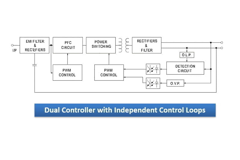
Wide input single stage LED driver uses the topology of flyback, which is a very cost effective and high efficiency design. This circuit design uses single transformer to achieve the high PF with normally 100-277Vac and good output constant current regulation. (Picture2,Principle Diagram)It is very widely used in the driver designs with less than 50W power.

Inherent drawbacks of Flyback
However, there are two inherent drawbacks of this topology, one is the very large current ripple and the other is that PF varies greatly with LED load characteristics. We will talk about the current ripple in another video and today we focus on the PF. We know that in single stage designs, PF is actually determined by the control loop, which makes the input current follow up with the input voltage, the more overlap they have, the higher PF we get.But it is a pity that the whole feedback control loop changes with the LED equivalent impedence greatly, while the impedence is determined by the LED V-I characteristic .

How to find the difference?
So when light engineers find the big difference between the tested value and the announced value, the first thing to do is to understand whether it is a single stage design. If it is, engineers just need to make sure the PF value is sufficient with the LED chips they use, and if not, there should be some quality problems with the driver or the driver is not well designed. For two stage designs, the jobs are very clear that the first stage makes sure PF is OK and the second stage regulates the output current. The second stage is usually little affected by the load because it has the constant voltage input and the control loops is very quick and stable.
So that is the story between Power factor and LED load, if you have questions, please dont hesitate to contact with sales@uPowerTek.com, or visit www.uPowerTek.com